xFUME™ ADVANCED 115V – CSA
4 Product description
EN
-
9
4 Product description
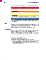
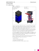
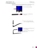
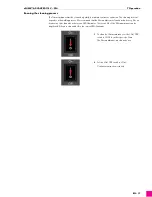
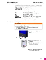
4.1 Assembly and use
The device is a component of a welding system. The device is used for manual welding and automated
welding/robot welding. Welding fumes are produced during the welding process. They are filtered and
cleaned by the filter cartridges inside the device. The device can be used to extract fumes and dust when
welding or cutting steel with an alloy content of nickel and chrome under 30%.
The device is equipped with an automatic starting function. Together with a current clamp, the automatic
starting function switches on extraction automatically when the welding process starts. Once the welding
process begins, the device receives a signal from the current clamp and automatically starts the fume
extraction process. Use of the automatic starting function extends the service life of the device.
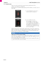
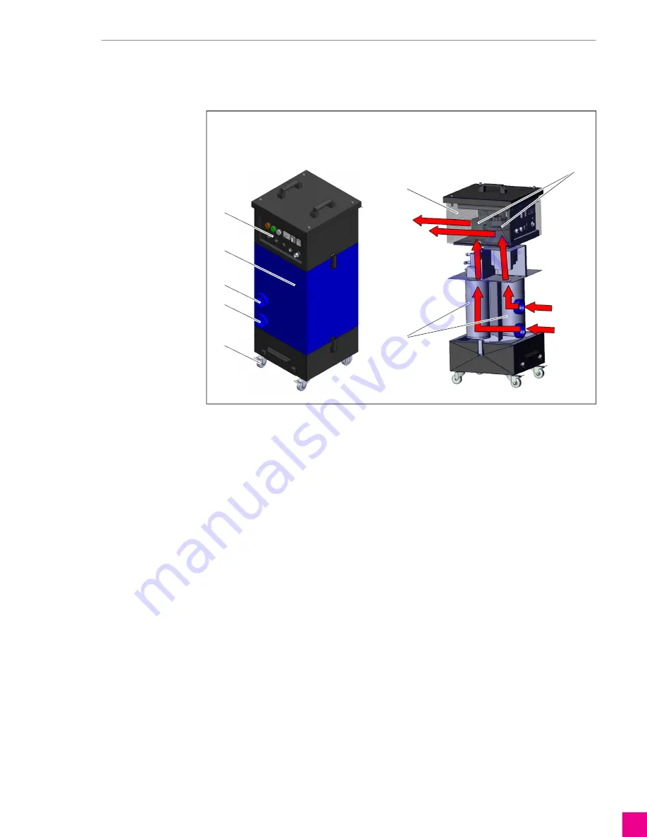
Two powerful turbines
draw the welding fumes in via intake fittings
located in the middle section of
the device. The welding fumes are pressed through filter membranes in the filter cartridges
. The dust and
debris stay stuck to the filter material. The cleaned air is sent through the top section of the device and
returned to the environment through exhaust louvers
The device is equipped with two rotary nozzles, which with the help of a pulse of pressurized air, blow dirt
and debris out of the filter membranes. A collection container collects the dirt and debris.
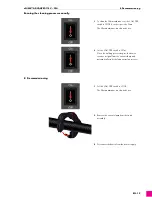
The following extraction devices can be connected to the device:
— Fume extraction torch
— Welding torch with external extraction systems
— Funnel-shaped nozzle with magnetic bracket
A maximum of two fume extraction torches may be attached to the device.
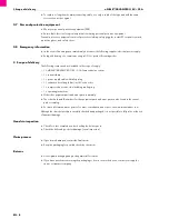
Abb. 2
Assembly and use
A
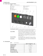
Control elements and connections
B
Compressed air connection
C
2× air intake fittings
D
4× castors
E
Air exhaust louver
F
2× turbines
G
2× filter cartridges
E
F
G
A
C
C
B
D


