User’s manual
The Ability system
11
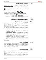
The list of faults signalled on the yellow fault LED
can be found in the
table in
Appendix C, Fault signals
.
Following is the list of events which cause the Red System Alarm LED
to blink:
•
Open panel tamper
•
Dislodged panel tamper
•
Expansion tamper
•
Keypad Tamper
•
Reader Tamper
•
Expansion Loss
•
Keypad Loss
•
Reader Loss
•
False key
2-3-6
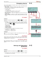
Signalling on the Buzzer
The buzzer signals the running entry, exit and pre-arm time (refer to
Appendix A, Technical terminology and Glossary
) of enabled partitions.
2-3-7
Emergency status
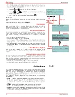
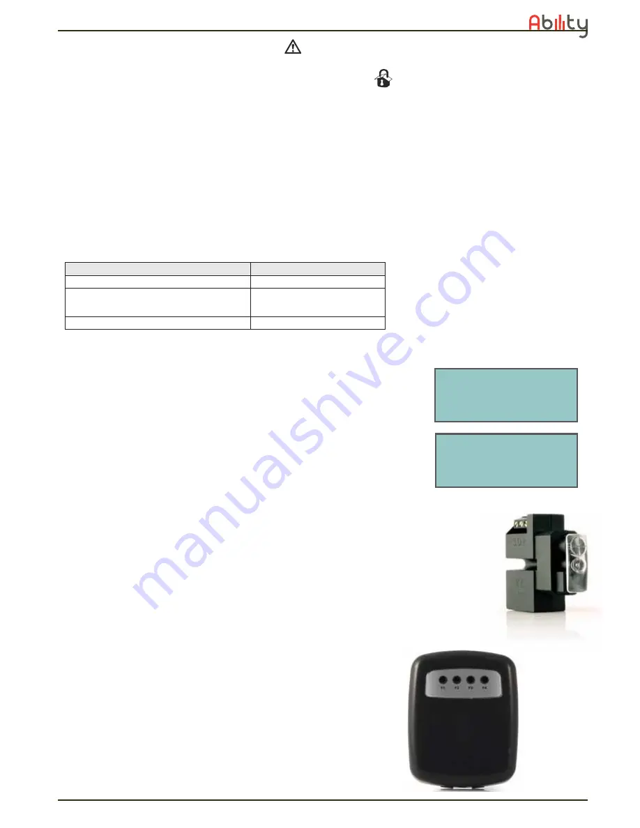
In the event of keypad configuration error or communication error between
the system peripherals, the display will show one of the screens opposite.
If this occurs, you must contact your installer immediately and get the fault
cleared.
2-4
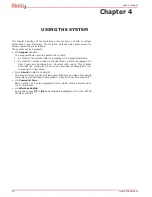
Reader - nBy
The Ability intrusion control panels manage nBy/S and nBy/X readers.
The proximity reader is the easiest way for users to interact with the Ability
intrusion control system.
The nBy/S model has been especially designed to mount to all types of
surface by means of just two screws. It is also IP34 rated (heavy duty) and
therefore suitable for outdoor use.
It is equipped with a buzzer and 4 LEDs:
•
F1
- Red
•
F2
- Blue
•
F3
- Green
•
F4
- Yellow
The Universal flush-mount nBy/X (
Patent Pending
) has been especially
designed to integrate with all brands of cover plates.
It is equipped with 4 LEDs (red, blue, green and yellow).
Readers do not provide the same extent of system control as keypads,
however, these devices are quick and easy-to-use and are extremely useful
when carrying out day-to-day operations (arm/disarm partitions, etc.).
Readers are usually located near the main entry/exit points of the
protected building. These devices allow system access to valid keys only.
The system readers are capable of recognizing the customized (personal)
parameters of each individual user key. Each reader is enabled to operate
on specific partitions, whereas each key is enabled to operate only on the
Buzzer signal
Description
8 pulses with 5 second pause
Entry time
3 pulses with 5 second pause;
4 short pulses with 5 second pause during the
final 20 seconds of the Exit Time
Exit time
1 pulse with 5 second pause
Pre-arm time
- n C o d e S -
F W R E L E A S E 1 . 0 0
N O C O M M U N I C A T I O N
K 0 1
- n C o d e S -
F W R E L E A S E 1 . 0 0
N O T E N R O L L E D
K 0 1


