3.3
Impella
®
System for Use During Cardiogenic Shock
3.3
SYSTEM CONFIGURATIONS
Initial set-up configuration for Impella
®
2.5 and Impella CP
®
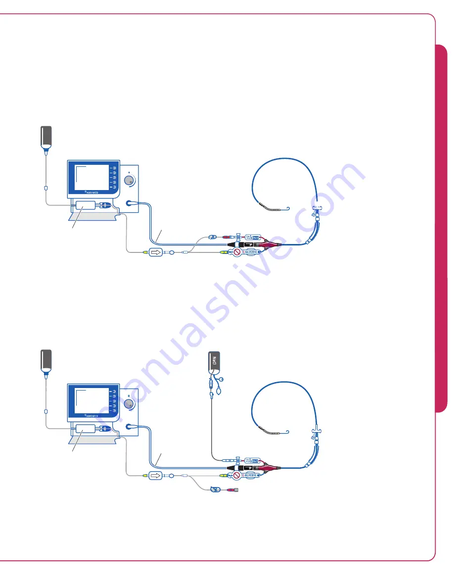
Figure 3.2a illustrates how the Automated Impella
®
Controller connects to the Impella
®
2.5 or
Impella CP
®
Catheter and accessory components in the initial set-up configuration.
Dextrose
Solution
Automated Impella
®
Controller
Purge Cassette
Impella
®
Catheter
Y-Connector
D20
D20
Connector Cable
Figure 3.2a Set-up Configuration of the Automated Impella
®
Controller, Impella
®
2.5 or
Impella CP
®
Catheter, and Accessories (Impella CP
®
shown)
Standard configuration for Impella
®
2.5 and Impella CP
®
Figure 3.2b illustrates the standard configuration of the Impella
®
2.5 or Impella CP
®
Catheter,
Automated Impella
®
Controller, and accessory components.
Dextrose
Solution
Automated Impella
®
Controller
Purge Cassette
Impella
®
Catheter
Y-Connector
D20
Sodium Chloride (NaCl)
Solution in Pressure Bag
Connector Cable
Figure 3.2b Standard Configuration of the Automated Impella
®
Controller, Impella
®
2.5
or Impella CP
®
Catheter, and Accessories (Impella CP
®
shown)
3
TH
E I
M
P
E
LL
A
®
C
A
TH
E
TE
R
A
N
D
A
U
TO
MA
TED
I
M
P
EL
LA
®
C
O
N
TRO
LL
E
R
3
TH
E I
M
P
E
LL
A
®
C
A
TH
E
TE
R
A
N
D
A
U
TO
MA
TED
I
M
P
EL
LA
®
C
O
N
TRO
LL
E
R
Summary of Contents for Impella 2.5
Page 4: ......
Page 8: ......
Page 10: ......
Page 12: ......
Page 15: ...2 WARNINGS AND CAUTIONS WARNINGS 2 1 CAUTIONS 2 3...
Page 16: ......
Page 22: ......
Page 38: ......
Page 40: ......
Page 108: ......
Page 171: ......
Page 173: ......
Page 181: ......
Page 183: ......
Page 201: ......
Page 203: ......
Page 205: ......
Page 210: ...INDEX TBD...


