


Installing the Mainboard
2-5
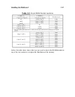
J6 - Turbo switch LED connector
This connector has a specific orientation. Connect the two-thread turbo switch
LED plug to the J6 connector pins on the mainboard.
Pin number
Name or significance of signal
9
Anode terminal of Turbo LED
8
Cathode terminal of Turbo LED
The
“
hardware Turbo LED
”
indicates the status of hardware
operating speed.
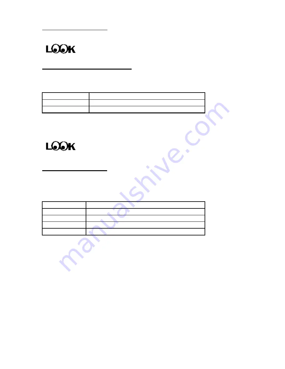
J5 - IDE LED connector
This connector has a specific orientation. Connect the two-thread IDE LED
connector cable attached to the case to the IDE LED connector on the
mainboard.
Pin number
Name or signifigance of signal
1
LED
’
s Cathode
2
LED
’
s Anode
3
LED
’
s Anode
4
LED
’
s Cathode
Computer
knowledge
Summary of Contents for AB-AR5
Page 2: ...Appendix F Technical Support ...
Page 6: ...1 4 Chapter 1 Layout diagram Fig 1 1 Layout diagram ...
Page 8: ...1 6 Chapter 1 ...
Page 28: ...2 20 Chapter 2 ...
Page 74: ...Appendix C C 2 ...
Page 76: ...Appendix D D 2 ...


