


Installing the Mainboard
2-9
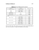
JP7 - Infrared remote Connectors Watch the pin number and the orientation
This has a specific orientation. Your mainboard supports this feature, but you
must buy the infrared remote device as an option.
Pin number
Name of the signal or signification
1
+5VDC
2
No connection
3
Receive data
4
Ground
5
Transmit data
I/O Port connectors Watch the pin number and the orientation
Connector name
Pin number
Name of the peripheral connected
IDE 1
40
IDE Channel 1
IDE 2
40
IDE Channel 2
FDC
34
Floppy Disk connector
LPT
26
Parallel port connector
COM1
10
Serial port COM1 connector
COM2
10
Serial port COM2 connector
USB
16
Universal Serial Bus connector
Summary of Contents for AB-AR5
Page 2: ...Appendix F Technical Support ...
Page 6: ...1 4 Chapter 1 Layout diagram Fig 1 1 Layout diagram ...
Page 8: ...1 6 Chapter 1 ...
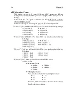
Page 28: ...2 20 Chapter 2 ...
Page 74: ...Appendix C C 2 ...
Page 76: ...Appendix D D 2 ...


