


2-18
Chapter 2
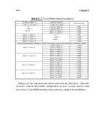
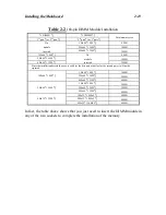
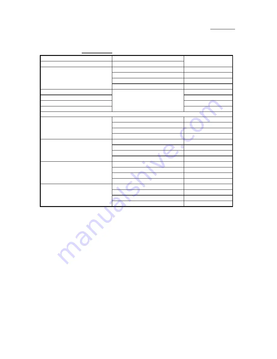
Table 2-1
72-pin SIMM Module Installation
¡i
SIMM1, SIMM2
¡j
¡i
SIMM3, SIMM4
¡j
1
st
pair
¡i
or 2
nd
pair
¡j
2
nd
pair
¡i
or 1
st
pair
¡j
Total memory size
No
1Mx32
¡i
4Mx2
¡j
8MB
module
2Mx32
¡i
8Mx2
¡j
16MB
inserted
4Mx32
¡i
16Mx2
¡j
32MB
8Mx32
¡i
32Mx2
¡j
64MB
1Mx32
¡i
4Mx2
¡j
No
8MB
2Mx32
¡i
8Mx2
¡j
module
16MB
4Mx32
¡i
16Mx2
¡j
inserted
32MB
8Mx32
¡i
32Mx2
¡j
64MB
Since the installation described above is valid for the first pair as well as for the second pair, it will not be repeated.
1Mx32
¡i
4Mx2
¡j
16MB
1Mx32
¡i
4Mx2
¡j
2Mx32
¡i
8Mx2
¡j
24MB
4Mx32
¡i
16Mx2
¡j
40MB
8Mx32
¡i
32Mx2
¡j
72MB
1Mx32
¡i
4Mx2
¡j
24MB
2Mx32
¡i
8Mx2
¡j
2Mx32
¡i
8Mx2
¡j
32MB
4Mx32
¡i
16Mx2
¡j
48MB
8Mx32
¡i
32Mx2
¡j
80MB
1Mx32
¡i
4Mx2
¡j
40MB
4Mx32
¡i
16Mx2
¡j
2Mx32
¡i
8Mx2
¡j
48MB
4Mx32
¡i
16Mx2
¡j
64MB
8Mx32
¡i
32Mx2
¡j
96MB
1Mx32
¡i
4Mx2
¡j
72MB
8Mx32
¡i
32Mx2
¡j
2Mx32
¡i
8Mx2
¡j
80MB
4Mx32
¡i
16Mx2
¡j
96MB
8Mx32
¡i
32Mx2
¡j
128MB
Perhaps you have already found out the rules from the table above. This table,
we belive, contains all possible configurations. In fact, you just need to insert
two or four 72-pin SIMM modules in the socket to complete the installation.
Summary of Contents for AB-AR5
Page 2: ...Appendix F Technical Support ...
Page 6: ...1 4 Chapter 1 Layout diagram Fig 1 1 Layout diagram ...
Page 8: ...1 6 Chapter 1 ...
Page 28: ...2 20 Chapter 2 ...
Page 74: ...Appendix C C 2 ...
Page 76: ...Appendix D D 2 ...


