background image

Installing the Motherboard 


User’s Manual 

3-5

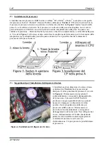
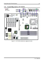
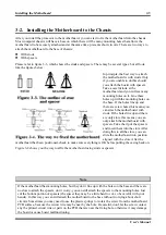
3-2.  Installing the Motherboard to the Chassis 

After you install the processor to the motherboard, you can start to fix the motherboard into the chassis. 
Most computer chassis will have a base on which there will be many mounting holes that allows the 
motherboard to be securely attached and at the same time, prevents short circuits. There are two ways to 
attach the motherboard to the base of chassis: 
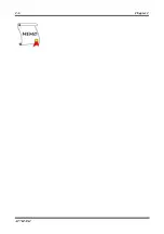
 With 

studs 

 With 

spacers 

Please refer to figure 3-3, which shows the studs and spacers. There may be several types, but all look 
like the figures below:


In principle, the best way to attach 
the motherboard is with studs. Only 
if you are unable to do this should 
you attach the board with spacers. 
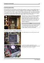
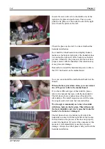
Take a careful look at the 
motherboard and you will see many 
mounting holes on it. Line these 
holes up with the mounting holes on 
the base. If the holes line up and 
there are screw holes this means you 
can attach the motherboard with 
studs. If the holes line up and there 
are only slots, this means you can 
only attach the motherboard with 
spacers. Take the tip of the spacers 
and insert them into the slots. After 
doing this to all the slots, you can 
slide the motherboard into position 
aligned with the slots. After the 

motherboard has been positioned, check to make sure everything is OK before putting the casing back on. 

Figure 3-4 shows you the way to affix the motherboard using studs or spacers. 


Note 

If the motherboard has mounting holes, but they don’t line up with the holes on the base and there are 
no slots to attach the spacers, don’t worry, you can still attach the spacers to the mounting holes. Just 
cut the bottom portion of spacers (the spacer they may be a little hard to cut, so be careful with your 
hands). In this way you can still attach the motherboard to the base without worrying about short 
circuits. Sometimes you may need to use the plastic springs to isolate the screw from the motherboard 
PCB surface, because the circuit wire may be near by the hole. Be careful, don’t let the screw contact 
any the printed circuit wire or parts on the PCB that are near the fixing hole, otherwise it may damage 
the board or cause board malfunctioning. 

Summary of Contents for AB-AT7-MAX2

Page 1: ...cidental or consequential damages arising from any defect or error in this manual or product Product names appearing in this manual are for identification purpose only and trademarks and product names or brand names appearing in this document are the property of their respective owners This document contains materials protected under International Copyright Laws All rights reserved No part of this...

Page 2: ......

Page 3: ...ND DURON CPU 3 2 3 2 INSTALLING THE MOTHERBOARD TO THE CHASSIS 3 5 3 3 INSTALLING SYSTEM MEMORY 3 6 3 4 CONNECTORS HEADERS AND SWITCHES 3 7 CHAPTER 4 INTRODUCING THE BIOS 4 1 4 1 CPU SETUP SOFT MENU III 4 3 4 2 STANDARD CMOS FEATURES SETUP MENU 4 6 4 3 ADVANCED BIOS FEATURES SETUP MENU 4 10 4 4 ADVANCED CHIPSET FEATURES SETUP MENU 4 13 4 5 INTEGRATED PERIPHERALS 4 21 4 6 POWER MANAGEMENT SETUP MEN...

Page 4: ...1 APPENDIX B AUDIO DRIVERS INSTALLATION FOR WINDOWS 2000 B 1 APPENDIX C LAN DRIVER INSTALLATION FOR WINDOWS 2000 C 1 APPENDIX D USB 2 0 DRIVERS INSTALLATION FOR WINDOWS 2000 D 1 APPENDIX E INSTALLING THE HARDWARE MONITOR SYSTEM E 1 APPENDIX F BIOS UPDATE GUIDE F 1 APPENDIX G TROUBLESHOOTING NEED ASSISTANCE G 1 APPENDIX H HOW TO GET TECHNICAL SUPPORT H 1 ...

Page 5: ...及 Duron 處 理器使用 支援 AMD Socket A 架構的處理器 並支援最高至 2 GB 容量的記憶體 必需是非緩衝 式 Unbuffered 且非 ECC 的 PC 2700 PC 3200 記憶體模組 或是 3 5 GB 必需是非緩衝式 Unbuffered 且非 ECC 的 PC 1600 PC 2100 記憶體模組 如果您想要瞭解這片主機板更詳細 的資訊 請參閱我們的完整版使用手冊 裡面會有詳盡的說明 此快速安裝手冊是給有經驗的系統 組裝者使用 如果這是您第一次嘗試來組裝您的電腦系統 我們建議您先去閱讀完整版的使用手 冊 或是詢問技術人員來幫助您組裝您的電腦系統 1 AT7 MAX2 主機板主要元件配置圖 圖 1 顯示了 AT7 MAX2 主機板主要元件的配置 此配置圖僅供您參考使用 圖 1 AT7 MAX2 主機板的主要元件配置圖 ...

Page 6: ... A 插座為止 請參見圖 3 同時您必需檢視處理器的 溫度偵測熱敏電阻的高度 如果有的話 然後再小心的將 AMD Athlon 或是 Duron 處理器依 前述的方法正確地安裝到 Socket A 腳座上去 3 安裝散熱裝置的提示 安裝散熱器與散熱風扇是必需的 這樣可以讓您 的處理器能夠適當地散熱 請參見圖 4 未安 裝散熱裝置可能導致處理器過熱 並且會損壞您 的處理器 AMD Socket A 處理器在運作時會產生 大量的熱量 所以您需要使用專門為 AMD Socket A 處理器設計的大型散熱風扇 否則可能會導致 過熱並且會損壞您的處理器 處理器風扇未裝置 妥當並且風扇電源線尚未連接妥當之前 請不要 把 ATX 電源供應器的電源纜線連接到主機板上 面 如此將可避免一些潛在損壞處理器的可能性 圖 4 散熱片及風扇的安裝示意圖 4 將主機板安裝到機殼上 當您將處理器安裝到主機板上之後 您便...

Page 7: ...將記憶體模組依照 DIMM1 至 DIMM4 的順序妥善地安裝於記憶體插槽 6 連接器 連接頭以及其它附加卡的安裝 在任何一部電腦機殼的裡面 都必需連接一些纜線與插頭 這些纜線與插頭通常都是一對一的連接 至主機板的連接埠上 您必需注意任何一條纜線的連接方向 如果可能的話 請一併注意連接埠第 一根針腳的位置 您將會安裝一些特殊功能的附加卡到主機板上面 像是 SCSI 卡或是 AGP 顯示 卡等等 當您將它們安裝到主機板上適當的插槽之後 請以螺絲將這些附加卡與機殼背板牢牢地固 定好 避免有鬆動的情況發生 如您想要瞭解相關且更為詳細的資訊 請參閱我們的完整版使用手 冊 裡面會有詳盡的說明 7 將電源供應器的電源線連接頭與主機板上的 ATX1 以及 ATX2 連接頭連接起來 AT7 MAX2 設計有兩個電源供應連接頭 ATX1 以及 ATX2 這與一般主機板所採用的電源設 計方式不太相同 它可以使...

Page 8: ...ATX2 連接頭上面 請記住您必 需將來自 ATX 電源供應器的電源供應纜線連接頭牢牢地插到主機板上的 ATX1 以及 ATX2 連接頭 上面 並確認其連接頭有良好連接 注意 請注意接腳的位置及方向 8 處理器參數的設定 SOFT MENU III 當您將所有的硬體安裝完畢以後 就可以開啟電腦的電源並進入 BIOS 的選項 請選擇 SoftMenu III Setup 的項目以進行處理器參數的設定 如您想要瞭解相關且更為詳細的資訊 請參閱我們的 完整版使用手冊 裡面會有關於 BIOS 各種項目設定的詳細說明 ...

Page 9: ...造をサポートして 最大 2 GB バッファなし 非 ECC PC 2700 PC 3200 または 3 5 GB バ ッファなし 非 ECC PC 1600 PC 2100 までの DDR DIMM メモリモジュールをサポートします このマザーボードの詳細については ユーザーズマニュアルの完全版を参照してください この クイックインストールガイドは 経験あるシステム構築者向けに書かれました 今回始めてコン ピュータシステムをセットアップする方は まず完全版のマニュアルをお読みになるか 専門技 術者に連絡してコンピュータシステムのセットアップを行うようお勧めします レバー 1 AT7 MAX2 マザーボードの配置 図 1 では AT7 MAX2 のレイアウト図を示しています 参考のために この図ですべての主要な コンポーネントを表示します 図 1 AT7 MAX2 レイアウト図 ...

Page 10: ...を変えると Socket A に完全 に差し込まれます 図 3 をご覧ください 同時に プロセッサの温度検出サーミスタの高さもチ ェックしてください マザーボードにこのコンポーネントが搭載されている場合 その後で プ ロセッサを Socket A にゆっくり差し込むことができます 3 ヒートシンクの取り付けに関するヒント ヒートシンクと冷却ファンの取り付けは コン ピュータから熱を分散させるために必要となり ます 図 4 参照 これらのアイテムを取り付け ないと 過熱してプロセッサが破損する原因と なります AMD Socket A プロセッサは動作中に 高熱を発生するため AMD Socket A プロセッサ 用に特別に設計された大きなヒートシンクが必 要となります そうでないと 過熱してプロセ ッサが破損することもあります プロセッサフ ァンとその電源ケーブルを正しく取り付けるま では...

Page 11: ...2100 の DDR DIMM メモリモジュールです ボードには 4 つのメモリモジュールソケットが搭載されて います 合計 8 バンク 図に示すように 拡張ソケットに DDR DIMM モジ ュールを挿入します モジュールがソケットに どのように固定されるか ご注意ください 詳 細については 図 5 を参照してください これ は DDR DIMM モジュールが誤った方向に装着で きないようにするためのものです DDR DIMM モ ジュールを DDR DIMM ソケットにしっかりと押し 込みます モジュールが DDR DIMM ソケットに最 後まで挿入されていることをご確認ください これらのモジュールに対して DIMM1 から DIMM4 まで順番に差し込むことをお勧めします 6 コネクタ ヘッダ スイッチおよびアダプタ コンピュータのケース内部には 複数のケーブルやプラグを接続できます...

Page 12: ...20A 5VDC の容量で またいくつかの特 殊機能をサポートする場合は最低 720mA 5VSB で 新設計の ATX12V1 12VDC 電源をサポートで きます ATX 電源装置から出るコネクタを ATX1 と ATX2 コネクタに接続します 汎用設計の ATX 電源装 置は ATX12V1 コネクタを装備していないため ATX2 コネクタには何も接続する必要はありませ ん ATX 電源装置から出るコネクタを ATX1 と ATX2 コネクタの端にしっかり押し込み 正しく 接続されていることを確認してください 注 ピンの位置と方向をよく確認してください 8 CPU のセットアップ SOFT MENU III ハードウェアの取り付けが完了したら コンピュータの電源をオンにし BIOS アイテム SoftMenu III セットアップ に移動して プロセッサのパラメータをセットアップしま...

Page 13: ...DDR DIMM Speichermodule Beziehen Sie sich bitte für detaillierte Informationen über diese Hauptplatine auf die vollständige Version des Benutzerbuchs Diese Schnellinstallationsanleitung ist für erfahrene Systemaufbauer gedacht Ist es Ihr erster Versuch ein Computersystem aufzubauen dann empfehlen wir Ihnen zuerst das vollständige Benutzerhandbuch zu lesen oder einen Techniker zum Aufbauen des Syst...

Page 14: ...des Prozessortemperaturerkennungsthermistors falls Ihre Hauptplatine diese Komponente besitzt Wenn alles in Ordnung ist stecken Sie bitte den Prozessor langsam in den Socket A ein 3 Hinweise zur Installation des Kühlkörpers Ein Kühlkörper und Lüfter ist erforderlich um die Hitze des Prozessors zu vertreiben siehe Abb 4 Wurden die zwei Vorrichtungen nicht installiert kann eine Überhitzung und ein S...

Page 15: ...e Setzen Sie das DDR DIMM Modul in den Erweiterungssockel wie im Bild gezeigt Achten Sie auf die Ausrichtung des Moduls im Sockel Bild 5 zeigt Details Dies stellt sicher dass das DDR DIMM Modul nur in eine Richtung hineinpaßt Drücken Sie das DDR DIMM Modul in den DDR DIMM Sockel wobei Sie darauf achten dass das Modul hinterher komplett fest im Sockel sitzt Für diese Module empfehlen wir die Bestüc...

Page 16: ...ondereffekte Verbinden Sie die Stecker der ATX Stromversorgung mit dem ATX1 und ATX2 Anschluss Die übliche ATX Stromversorgung hat keinen ATX12V1 Stecker so dass Sie nichts mit dem ATX2 Anschluss verbinden müssen Drücken Sie bitte die Stecker der ATX Stromversorgung fest in den ATX1 und ATX2 Anschluss um eine gute Verbindung sicherzustellen Anmerkung Achten Sie auf Position und Ausrichtung der Pol...

Page 17: ...ves à cette carte mère plus détaillées veuillez vous référer à notre version complète du manuel utilisateur Ce guide d installation rapide est créé pour les assembleurs système expérimentés S il s agit de votre premier essai pour installer un ordinateur nous vous suggérons de lire d abord le manuel en version complète ou de demander l aide d un technicien pour vous aider à configurer le système or...

Page 18: ...e du processeur si votre carte mère possède ce composant Ensuite vous pouvez insérer lentement le processeur dans le Socket A 3 Conseils Relatifs à l Installation du Dissipateur Thermique Installer un dissipateur thermique et un ventilateur de refroidissement est nécessaire pour que la chaleur se dégage de votre processeur Voir Figure 4 Ne pas installer ces composants pourrait provoquer une surcha...

Page 19: ...n Remarquez comment le module est positionné par une encoche dans son support Vous pouvez vous référer à la Figure 5 pour les détails Cela vous assure qu il n y a qu une seule façon de brancher le module de mémoire DDR DIMM Pressez fermement le module DDR DIMM dans son emplacement DDR DIMM assurez vous que le module est complètement inséré dans son support DDR DIMM Pour ces modules nous vous suggé...

Page 20: ...s spéciales Branchez ici l alimentation électrique ATX sur les connecteurs ATX1 et ATX2 les unités d alimentation électriques ATX conventionnelles ne possèdent pas de connecteur ATX12V1 aussi n avez vous pas besoin de brancher quoi que ce soit sur le connecteur ATX2 N oubliez pas que vous devez pousser fermement sur le connecteur de l unité d alimentation pour la brancher sur les connecteurs ATX1 ...

Page 21: ...е без контроля четности PC 2700 PC 3200 или 3 5 Гбайт небуферированные без контроля четности PC 1600 PC 2100 Более подробные сведения о материнской плате приведены в руководстве пользователя Краткое руководство по установке предназначено для опытных специалистов Если вы собираете компьютер впервые ознакомьтесь сперва с руководством пользователя или попросите техника помочь в настройке компьютерной...

Page 22: ...мя проверьте высоту температурного датчика если он установлен на материнской плате Теперь можно установить процессор в гнездо Socket A 3 Советы по установке радиатора Установка радиатора и вентилятора необходима для рассеивания тепла от процессора см рис 4 Неустановка радиатора и вентилятора может привести к перегреву и повреждению процессора Процессор AMD Socket A сильно нагревается в процессе ра...

Page 23: ...и всего восемь банков Установите модуль памяти DDR DIMM в гнездо как показано на рисунке Обратите внимание на ориентацию модуля в гнезде Установка подробно проиллюстрирована на рисунке 5 Ключевой элемент гарантирует что модуль DDR DIMM будет установлен единственным образом Установите модуль памяти DDR DIMM в гнездо DDR DIMM и убедитесь что модуль установлен до упора Рекомендуется заполнять гнезда ...

Page 24: ...мум 720 мА при напряжении в режиме ожидания 5 В и наконец для использования некоторых дополнительных возможностей Подсоедините разъем блока питания АТХ к разъемам АТХ1 и АТХ2 Обычный блок питания АТХ не имеет разъема ATX12V1 так что нет необходимости подключать что либо к разъему ATX2 Помните что следует вставлять разъем блока питания с усилием до конца в разъемы АТХ1 и АТХ2 чтобы обеспечить хорош...

Page 25: ...i e dettagliate informazioni su questa scheda madre si prega di fare riferimento alla versione integrale del Manuale utente Questa guida all installazione veloce è intesa per costruttori esperi di sistemi Se questa è la prima volta che si cerca di installare un sistema si consiglia di leggere innanzi tutto la versione integrale del manuale oppure di chiedere aiuto ad un tecnico per l installazione...

Page 26: ...mperatura se la scheda madre possiede questo elemento Poi è possibile inserire lentamente il processore nella presa Socket A 3 Suggerimenti per l installazione del dispersore di calore L installazione di un dispersore di calore e di una ventolina di raffreddamento è necessaria per dissipare il calore generano dal processore si veda la Figura 4 Diversamente si provocherà il surriscaldamento e conse...

Page 27: ...come mostrato dell illustrazione Notare come il modulo è imperniato nella presa Fare riferimento alla Figura 5 per dettagli Ciò assicura che ci sia un unico modo per collegare il modulo DDR DIMM Premere con fermezza il modulo DDR DIMM nello slot DDR DIMM assicurandosi che il modulo sia inserito completamente nello slot DDR DIMM Per questi moduli si suggerisce di inserire i chip elettronici in ordi...

Page 28: ...lcune funzioni speciali Collegare qui il connettore dall alimentazione ATX ai connettori ATX1 ed ATX2 l alimentazione di progettazione generale ATX non possiede il connettore ATX12V1 quindi non è necessario collegare nulla al connettoreATX2 Ricordarsi che è necessario spingere fino in fondo il connettore della sorgente d alimentazione ATX con i connettori ATX1 e ATX2 assicurando così un buon colle...

Page 29: ...w high speed interface almost doubles the Ultra DMA 66 burst data transfer rate to 133 Mbytes sec The result is maximum disc performance using the current PCI local bus environment Another benefit is the ability to connect four IDE devices to your system either through Ultra DMA 66 Ultra DMA 100 or Ultra DMA 133 With this you will have more flexibility to expand your computer system AT7 MAX2 s bui...

Page 30: ...o the future giving users a new level of system longevity and flexibility 2 2 Specifications 1 Processor Supports AMD Athlon XP 1500 2200 Socket A processors based on 200 MHz 266 MHz 100 MHz 133 MHz Double Data Rate Supports AMD Athlon 700 MHz 1 4 GHz Socket A processors based on 200 MHz 266 MHz 100 MHz 133 MHz Double Data Rate Supports AMD Duron 600 MHz 1 2 GHz Socket A processors based on 200 MH...

Page 31: ...ing 24 bit S P DIF OUT 8 LAN Onboard VIA VT6102 MAC controller and VT 6103 physical layer interface 10 100 Mb operation support ACPI and Wake on LAN User friendly driver included 9 ABIT Media XP Optional Supports SONY MS Memory Stick interface SD Secure Digital memory card interface Supports CF CompactFlash interface Both Type I Type II and IBM Microdrive 10 Internal I O Connectors 1 x AGP 5 x PCI...

Page 32: ...Hz 133 MHz that are used by specific PCI processor and chipset specifications Exceeding these standard bus speeds is not guaranteed due to the specific component specifications Specifications and information contained in this manual are subject to change without notice Note All brand names and trademarks are the property of their respective owners 2 3 Item Checklist Check that your package is comp...

Page 33: ...Introduction of AT7 MAX2 Features User s Manual 2 5 2 4 Layout Diagram for AT7 MAX2 Figure 2 1 AT7 MAX2 motherboard component location ...

Page 34: ...Chapter 2 AT7 MAX2 2 6 ...

Page 35: ...ds please remember to turn the ATX power supply switch off fully turn the 5V standby power off or take the power cord off Otherwise you may cause the motherboard components or add on cards to malfunction or be damaged User Friendly Instructions Please read our instructions carefully and follow them step by step Our objective is to enable the novice computer user to perform the installation by hims...

Page 36: ... you can easily fix the processor firmly into position Figure 3 1 shows you what the socket A looks like and how to open the lever The socket A has more pins than the socket 7 Therefore a Pentium level processor cannot be inserted into a socket A When you raise the lever you have to loosen the socket lock Please raise the lever to the end and prepare to insert the processor Next you need to align ...

Page 37: ... and cause circuit damage break socket hooks or damage the die on the top of processor Please follow the sequence metioned below Do Not inverse the sequence Otherwise you may have a situation like the photo on the left Because of the design of the CPU socket the left side hooks are not as strong as the right side hooks If you follow our suggestions you will prevent your processor and socket from d...

Page 38: ...therboard back into the chassis When all above procedures done you can connect the ATX power cable to the motherboard If you have different types of heatsink kit please refer to the manual that came with the heatsink kit The left photo shows another type of heatsink fix plate design The install sequences are still the same from right side to left side Just remember that We strongly recommand you t...

Page 39: ... up and there are only slots this means you can only attach the motherboard with spacers Take the tip of the spacers and insert them into the slots After doing this to all the slots you can slide the motherboard into position aligned with the slots After the motherboard has been positioned check to make sure everything is OK before putting the casing back on Figure 3 4 shows you the way to affix t...

Page 40: ... 64 MB 1 GB Total System Memory for Unbuffered Non ECC DDR DIMM PC 1600 PC 2100 64 MB 2 GB Total System Memory for Unbuffered Non ECC DDR DIMM PC 2700 PC 3200 64 MB 3 5 GB Generally installing DDR SDRAM modules to your motherboard is an easy thing to do You can refer to Figure 2 5 to see what a 184 pin PC 1600 PC 2100 and PC 2700 DDR SDRAM module looks like Unlike installing SIMMs DIMMs may be sna...

Page 41: ...icker will tell you which kind of structure module the DDR SDRAM is 3 4 Connectors Headers and Switches Inside the case of any computer several cables and plugs have to be connected These cables and plugs are usually connected one by one to connectors located on the motherboard You need to carefully pay attention to any connection orientation the cables may have and if any notice the position of t...

Page 42: ... is different from the regular one It can provide for power supply designed for Pentium 4 processors also can provide for general designed ATX power to connect to AT7 MAX2 It s a newly designed ATX12V1 12VDC power with 300W 20A 5VDC capacity at least for heavily loaded system and 720mA 5VSB at least for supporting some special features Attach the connector from the ATX power supply to the ATX1 and...

Page 43: ...of both slot sides If you insert an electroscope into the live wire slot the electroscope will light up Using a voltage meter you will find that the live wire slot will register a higher voltage If you reverse the polarity of AC plug it may affect the life of computer equipment or cause an electric shock when you touch the computer chassis We suggest that you plug the computer AC plug to a three h...

Page 44: ... master by initiating a data transfer If more than one master simultaneously tries to control the bus an arbitration procedure decides which master gets priority You can connect the devices which utilizes the SM Bus Note Watch the pin position and the orientation 4 TCPU1 TSYS1 Temperature Thermistor The TCPU1 is used to detect the CPU temperature The TSYS1 is used to detect the system environment ...

Page 45: ... USB3 USB4 headers supports USB 2 0 specification function please use the special USB cable design for USB 2 0 specifications Otherwise it may cause an unstable or signal error situation 6 IEEE1 Header IEEE 1394 Header This header is reserved for connection to the ABIT Media XP product Optional The Media XP can provide the total solution for the front panel connections It provided a various functi...

Page 46: ...stall the motherboard make sure this jumper is set for normal operation pin 1 and 2 shorted See figure below Note Watch the pin position and the orientation Note Before you clear the CMOS you have to first turn the power off including the 5V standby power Otherwise your system may work abnormally After updating your BIOS and before boot up please clear the CMOS first Then put the jumper to its def...

Page 47: ... hold the reset button for at least one second to reset the system PN 1 Pin 15 17 19 21 Speaker Header Attach the cable from the system speaker to this header PN 1 Pin 2 4 Suspend LED Header Insert the two threaded suspend LED cable into this header If you install it in the wrong direction the LED light will not illuminate correctly Note Watch the Suspend LED pin position and the orientation PN 1 ...

Page 48: ...er 5V PIN 16 PWR LED PIN 17 Speaker GND PIN 18 No Pin PIN 19 Speaker GND PIN 20 PWR LED PIN 21 Speaker Driver PIN 22 No Connection PN1 PIN 23 No Pin PN1 PIN 24 No Connection 9 FPIO2 Header Front Panel Input Output Signals Header You ll see this header on AT7 MAX2 motherboard This header is designed to connect the ABIT Media XP product This header can provide the analog audio output signals for fro...

Page 49: ...n set the S2K bus the bus between CPU and North Brige operating mode as figure below When setting jumper CROM to Strapping from boot ROM Default the timing of S2K bus is controlled by the internal boot rom and you enable the option CPU Fast Command Decode in the BIOS The system performance will increase When the jumper is set to Strapping from Hardware the timing of S2K bus is controlled by CPU ha...

Page 50: ...th of ribbon cable to the IDE port on motherboard and the other two ends gray and black connector at the shorter length of the ribbon cable to the connectors on hard drives AT7 MAX2 s built in HighPoint HPT 374 chipset gives you the capability to support Ultra DMA 133 It provides two IDE channels IDE3 IDE4 that also support Ultra DMA 133 specifications and it allows for four additional IDE devices...

Page 51: ...high speed and high performance mass storage devices Thus we suggest that you don t connect non disk devices that use ATA ATAPI interfaces such as a CD ROM to HPT 374 IDE connector IDE3 and IDE4 14 J1 and J2 Connectors Serial ATA Connectors This motherboard provides two Serial ATA ports J1 J2 to connect two Serial ATA devices in Serial ATA 150 mode by special Serial ATA ribbon cables Each cable ha...

Page 52: ... USB2 and U30 This motherboard provides six USB ports on back panel of motherboard These six USB ports are complient with USB 2 0 specification Attach the USB cable connector from the individual device to these connectors You can attach USB devices such as a keyboard mouse printer portable HDD scanner digital speakers monitor hub digital camera joystick etc to one of each USB connector You must ma...

Page 53: ...oofer channel speakers or center subwoofer channel amplifier correctly otherwise you may get the wrong sound positioning Mic In Connector You can connect the plug from the microphone to this connector Do not connect other audio or signal sources to this connector Line In Connector You can connect the TV adapter audio output signal or external audio sources like a CD walkman video camcorder VHS rec...

Page 54: ...Chapter 3 AT7 MAX2 3 20 ...

Page 55: ...ash and sometimes you will even not be able to boot the computer after it has crashed We recommend that you do not change the parameters inside the BIOS unless you are very familiar with them If you are not able to boot your computer anymore please refer to the section CCMOS1 Header in Chapter 2 to see how to discharge the CMOS date When you start the computer the BIOS program controls it The BIOS...

Page 56: ...rsion may change periodically However most of the functions covered in this manual will work We suggest that you go to our WEB site often to see if there are new manual releases Then you can check the newly updated BIOS items Computer Knowledge CMOS Data Maybe you have heard somebody saying that his or her CMOS DATA was lost What is the CMOS Is it important The CMOS is the memory used to store the...

Page 57: ...isplay all the items that can be chosen for that option Figure 3 2 CPU SOFT MENU III CPU Name Is AMD Athlon tm XP AMD Athlon tm AMD Duron tm CPU Operating Speed This option sets the CPU speed Select the CPU speed according the type and the speed of your CPU For AMD Athlon XP Athlon and Duron processors you can choose the following settings This example is for AMD Athlon XP processor User Define 15...

Page 58: ...d bus speed is supported but not guaranteed due to the CPUspecs Ratio FSB AGP PCI Three options are available 3 2 1 4 2 1 5 2 1 This item lets you set the processor Front Side Bus AGP and PCI clock It correlates with the processor FSB clock you set Many of options are available you can choose the divider ratio you want If the setting is 3 2 1 In this case the AGP clock will be the processor FSB cl...

Page 59: ...OS Setup to set up CPU parameters again Attention After setting up the parameters and leaving the BIOS SETUP and having verified that the system can be booted do not press the Reset button or turn off the power supply Otherwise the BIOS will not read correctly the parameters will fail and you must enter SOFT MENU III again to set up the parameters all over again CPU Power Supply This option allows...

Page 60: ...mper on the mainboard called CROM pin 1 and pin 2 short then you can see this item appear in this menu 4 2 Standard CMOS Features Setup Menu This contains the basic configuration parameters of the BIOS These parameters include date hour VGA card floppy disk and HDD settings Figure 3 3A Standard CMOS Setup Screen Shot Date mm dd yy You can set the date in this item month mm date dd and year yy Time...

Page 61: ...then FORMAT the drive Most current HDDs have already been subjected to low level format at the factory so you can probably skip this operation Remember though the primary IDE HDD must have its partition set to active within the FDISK procedure If you are using an old HDD that is already formatted auto detection can t detect the correct parameters You may need to do a low level format or set the pa...

Page 62: ...end you use this mode Currently the BIOS can support the INT 13h extension function enabling the LBA mode to support hard disk drive capacities exceeding 8 4 GB Large Mode When the number of cylinders CYLs of the hard disk exceeds 1024 and DOS is not able to support it or if your operating system does not support LBA mode you should select this mode Auto Just let the BIOS detect your HDD access mo...

Page 63: ... 5 25in 720K 3 5 in 1 44M 3 5 in 2 88M 3 5 in Floppy 3 Mode Support Four options are available Disabled Driver A Driver B Both The default setting is Disabled 3 Mode floppy disk drives FDD are 3 5 drives used in Japanese computer systems If you need to access data stored in this kind of floppy you must select this mode and of course you must have a 3 Mode floppy drive Video You can select the VGA ...

Page 64: ...he partition table the BIOS will warn you that a boot virus is attempting to access the hard disk Quick Power On Self Test Two options are available Enabled or Disabled the default setting is Enabled After the computer has been powered on the BIOS of the motherboard will run a series of tests in order to check the system and its peripherals If the Quick Power on Self Test feature is enable the BIO...

Page 65: ...sabled When the computer boots up the BIOS detects if the system has a FDD or not When this item is set to Disabled if the BIOS detects no floppy drive it will display a floppy disk drive error message If this item is disabled the BIOS will skip this test Boot Up NumLock Status Off At boot up the Numeric Keypad is in cursor control mode On At boot up the Numeric Keypad is in numeric mode Default S...

Page 66: ...or Specification If you use an older OS for multi processors executing please set this option to 1 1 OS Select For DRAM 64MB Two options are available Non OS2 or OS2 The default setting is Non OS2 When the system memory is bigger than 64MB the communication method between the BIOS and the operating system will differ from one operating system to another If you use OS 2 select OS2 if you are using ...

Page 67: ...o boot up If you don t know the hardware very well use default values i e use the Load Fail Safe Defaults or Load Optimized Defaults option Figure 3 5A Advanced Chipset Features Setup Screen You can use the arrow keys to move between the items Use PgUP PgDn or key to change the values When you have finished setting up the chipset press ESC to go back to the main menu Note The parameters in this sc...

Page 68: ...trol Lower Screen Current FSB Frequency This item will show you the current system front side bus speed Current DRAM Frequency This item will show you the current DRAM bus speed DRAM Clock Five options are available By SPD 100 MHz 133 MHz 166 MHz 200 MHz The default setting is By SPD You can set the DRAM running speed but if your DRAM module does not support the set speed the system may be unstabl...

Page 69: ...failure to boot or fatal exception errors DRAM Timing Selectable Four options are available Manual By SPD Turbo Ultra The default setting is By SPD When set to By SPD the BIOS will read the DRAM module SPD data and automatically set to the values stored in it If you set to Manual the following five items will be available to let you make adjustments CAS Latency Time Four options are available 1 5 ...

Page 70: ... to adjust the data input strobe delay time of memory You can key in the HEX number into this section The minimum number is 0000 and maximum number is 00FF DDR DQS Output Delay Two options are available Auto or Manual The default setting is Auto If you set to Manual then the next item will be available Output Delay Value This item allows you to adjust the data output strobe delay time of memory Yo...

Page 71: ...T can let you get quick DRAM acess time than 3T and 3Tis a general DRAM setting Enhance DRAM Performance Two options are available Disabled or Enabled The default setting is Disabled This item can improve your system DRAM performance DRAM Command Rate Two options are available 2T Command or 1T Command The default setting is 2T Command When the host northbridge locates the desired memory address it...

Page 72: ...e The aperture is a portion of the PCI memory address range dedicated for graphics memory address space Host cycles that hit the aperture range are forwarded to the AGP without any translation See www agpforum org for AGP information AGP Data Transfer Rate Two options are available 4X 2X The default setting is 4X When you installed AGP 4X adapter If you installed the AGP adapter that supports AGP ...

Page 73: ...etting is Disabled This implements a single delay when writing to the AGP Bus When you set it to Enabled two wait states are used by the system allowing for greater stability AGP Master 1 WS Read Two options are available Disabled or Enabled The default setting is Disabled This implements a single delay when reading to the AGP Bus When you set it to Enabled two wait states are used by the system a...

Page 74: ...r Enabled The default setting is Enabled When you set it to Enabled it can enable PCI post write buffers to minimize PCI2 master read latency Vlink 8X Support Two options are available Disabled or Enabled The default setting is Enabled This item can let you enable the Vlink bus data transfer between northbridge and southbridge PCI Delay Transaction Two options are available Disabled or Enabled The...

Page 75: ...Default Screen Onboard FDD Controller Two options are available Disabled or Enabled The default setting is Enabled This is used to enable or disable the Onboard FDD Controller If you add a higher performance controller you will need to Disable this feature VIA OnChip IDE Device This item can let you sets several items concerning the VIA OnChip IDE device parameters Figure 3 6B OnChip IDE Device Sc...

Page 76: ... Ultra DMA is a DMA data transfer protocol that utilizes ATA commands and the ATA bus to allow DMA commands to transfer data at a maximum burst rate of 133 MB sec Disabled If you encounter the problem of using Ultra DMA devices you can try to set this item to Disabled Auto When you select Auto the system automatically determines the optimal data transfer rate for each IDE device Default Slave Driv...

Page 77: ...even you do not connect bootable devices on your computer system the system will searching the bootable file through the local network If system fined the bootable file on local network it will load it and use it to boot your computer system OnChip USB Controller Two options are available Disabled or Enabled The default setting is Enabled This should be enabled if your system has a USB device inst...

Page 78: ...a ATA 133 specifications If you set this controller to Enabled you can use IDE RAID functions inlcuding RAID 0 RAID 1 and RAID 0 1 This feature enables you to maximize your data storage performance and security For detailed information please refer to the Chapter 4 USB 2 0 Controller Two options are available Disabled or Enabled The default setting is Enabled This motherboard has the built in USB ...

Page 79: ...o video I O ports and drives and the operating status of the keyboard mouse and other device These are referred to as Power Management Events In cases where none of these events occur within setting time the system enters the power saving mode When one of the controlled events occurs the system immediately returns to normal mode and operates at its maximum speed 1 In the Main Menu select Power Man...

Page 80: ...rt for multiple wake up events see Table 4 6 1 Support for a front panel power and sleep mode switch Table 4 6 2 describes the system states based on how long the power switch is pressed depending on how ACPI is configured with an ACPI aware operating system System States and Power States Under ACPI the operating system directs all system and device power state transitions The operating system put...

Page 81: ...ssor is not executing instructions The processor complex context is not maintained Dynamic RAM context is maintained Power Resources are in a state compatible with the system S3 state All Power Resources that supply a System Level reference of S0 S1 or S2 are in the OFF state Devices states are compatible with the current Power Resource states Only devices which solely reference Power Resources wh...

Page 82: ...nt it to turn on your computer power Resume by OnChip USB Two options are available Disabled or Enabled The default setting is Disabled When set to Enabled any event affecting from onchip USB will awaken a system that has powered down Wakeup by PME of PCI Two options are available Disabled or Enabled The default setting is Disabled When set to Enabled any event affecting from PCI card PME will awa...

Page 83: ...returns the computer return to the previous power state 4 7 PnP PCI Configurations Setup Menu In this menu you can change the INT and IRQ of the PCI bus and other hardware settings Figure 3 8A PnP PCI Configurations Setup Menu Force Update ESCD Two options are available Disabled or Enabled The default setting is Disabled Normally you should leave this field Disabled Select Enabled to reset Extende...

Page 84: ... IRQ Resources If you have trouble in assigning the interrupt resources automatically you can select Manual to set which IRQis assigned to which PCI Device or Reserved it See the screen shot below IRQ Resources If you have trouble in assigning the interrupt resources automatically you can select Manual to set which IRQis assigned to which PCI device or reserve it See the screen shot below Figure 3...

Page 85: ...l function for when you want to fix the IRQ for a specific device For example if you want to move your hard disk to another computer and don t want to re install Windows NT or Windows 2000 you can simply specify the IRQ for the device installed on the new computer to fit the original computer settings This feature is for the operating system that will record and fix the PCI configuration status if...

Page 86: ...rocessor temperature exceeds the settings value system will force to shutdown to protect the processor not overheat CPU Warning Temperature Eight options are available Disabled 50 122 53 127 56 133 60 140 63 145 66 151 70 158 The default setting is Disabled You can set the processor warning temperature here If the processor temperature exceeds the settings value the system will give you an alarm m...

Page 87: ...to Load Optimized Defaults Y N N Pressing Y loads the default values that are factory settings for optimal performance system operations 4 11 Set Password Set Password Can enter but do not have the right to change the options of the setup menus When you select this function the following message will appear at the center of the screen to assist you in creating a password ENTER PASSWORD Type the pa...

Page 88: ...e required both at boot and at entry to Setup If set to Setup prompting only occurs when trying to enter Setup 4 12 Save Exit Setup Pressing Enter on this item asks for confirmation Save to CMOS and EXIT Y N Y Pressing Y stores the selections made in the menus in CMOS a special section of memory that stays on after you turn your system off The next time you boot your computer the BIOS configures y...

Page 89: ...oring RAID 0 1 operation For the striping operation the identical drives can read and write data in parallel to increase performance The Mirroring operation creates a complete backup of your files Striping with Mirroring operation offers both high read write performance and fault tolerance although requiring 4 hard disks in order to do so 5 2 RAID SETUP on the AT7 MAX2 Enter Advanced BIOS Features...

Page 90: ... to confirm or to modify Press Enter to confirm the selection Press Esc to return to top menu NOTE If you want to create a RAID 0 striping array or RAID 0 1 array all data in your hard disk will first be erased Please backup the hard disk data before creating a RAID array If you want to create a RAID 1 mirroring array please be sure which hard disk is the source disk and which one is the destinati...

Page 91: ...re are four modes to choose Note It is highly recommended to attach hard disks with the same brand and same model when defining a RAID array RAID 0 Striping for Performance This item is recommended for high performance usage Requires at least 2 disks RAID 1 Mirroring for Data Protection This item is recommended for data security usage Requires at least 2 disks RAID 0 1 Mirrored Striping This item ...

Page 92: ...o start creation 4 3 2 OPTION 2 Delete Array This item allows you to remove a RAID Array on this onboard IDE RAID controller Note After you have made and confirmed this selection all the data stored in the hard disk will be lost The entire partition configuration will be deleted too 4 3 3 OPTION 3 Create Delete Spare Create Spare In the menu zone select item 3 Create Delete Spare and press Enter t...

Page 93: ...4 Select Boot Disk This item allows you to select the boot disk among the hard disk s Use the up down arrow to select the menu option to Select Boot Disk and press Enter In the Channel Status select the channel you would like to set as bootable disk and press Enter an asterisk appears in the parentheses to indicate that the channel has been selected Tips We suggestion you to set the RAID function ...

Page 94: ...Chapter 5 AT7 MAX2 5 6 ...

Page 95: ...he program automatically If not you can go to the CD location and execute the execution file at the main directory of the CD After it has been executed you will see the screen below Step 2 Move the cursor to HPT 374 Driver and click on it You will go to the next screen Step 3 The InstallShield Wizard shows up and it will go to the next screen for a while Step 4 You will now see the welcome screen ...

Page 96: ...lation Step 8 Choose Yes I want to restart my computer now in the check box and click Finish restart your computer to finish the driver update Step 9 The Digital Signature Not Found menu appears Click Yes to continue This screen will show up again please click Yes to go on Step 10 Go to the Control Panel System Properties Device Manager Now you can see that the driver is installed under the item o...

Page 97: ...t you to press F6 key to specify an additional device Press F6 key and let Windows continue on with setup It will continue to scroll through various device listings for several minutes It will then prompt you to press the S key to add a device 2 Press S key and insert the HPT 374 driver diskette Press Enter when prompted and allow Windows 2000 to install the HPT 374 drivers 3 Windows 2000 will con...

Page 98: ...Chapter 6 AT7 MAX2 6 4 ...

Page 99: ...ode of the RAID function in a Windows environment making it easier and more user friendly than creating the RAID function in BIOS mode Please insert the AT7 MAX2 series CD into your CD ROM drive It should execute the program automatically If not you can go to the CD location and execute the execution file from the main directory of the CD After it is executed you will see the screen shot below Ste...

Page 100: ...d will add program icons to those program folders listed Click Next to go on Step 7 The system will start copying files You can see the percentage bar on the screen Step 8 Program ask you want to add a shortcut to startup folder or not We suggestion you choose Yes Step 9 When the installation is completed and if you don t want to lunch readme file Click Finish to end the setup Step 10 After the sy...

Page 101: ...e first screen you will see when you starting the software This is the Configuration Menu screen This is the Management Menu screen This is the View Menu screen For detailed information of this software you can refer to the Help menu It will provide you all the information of this software that you need to know ...

Page 102: ...7 4 Chapter 7 AT7 MAX2 ...

Page 103: ...2 SP2 or latest service pack to get the best system performance You can download SP2 at Microsoft WEB site Note Details of the or Windows 2000 operating system will not be mentioned in this manual If you have any problems with Windows 2000 installation operations or settings please refer to your Windows 2000 user s manual or other databases provided by Microsoft Corporation Insert the AT7 series C...

Page 104: ...detect and install the latest 4 in 1 drivers For users who are upgrading VIA Drivers we recommend installing the 4 in 1 using the Quickly Install mode as it will automatically detect and update the necessary drivers The following step we will describe the Normally Install mode procedure Step 6 This setup program will install three kinds of drivers Please check which drivers you want to install Whe...

Page 105: ... the install progress percentage Step 10 When the installation is complete the installer will ask you to restart your computer We suggest that you choose Yes I want to restart my computer now Then click the Finish button to restart your computer to finish the driver update Step 11 You can then check the Device Manager to see that the devices are properly installed ...

Page 106: ...A 4 Appendix A AT7 MAX2 ...

Page 107: ...ur Windows 2000 user s manual or other databases provided by Microsoft Corporation Insert the AT7 series CD into your CD ROM drive and it should execute the program automatically If not you can go to the CD location and execute the execution file at the main directory of the CD After it has been executed you will see the screen below Step 1 Move the cursor to Audio Driver and click on it You will ...

Page 108: ...puter now then click the Finish button to restart your computer to finish the driver updates Step 7 When system restarts and enters the operating system you can then check the Device Manager to see that the devices are properly installed Step 8 You can choose from Start Programs then from item Avance Sound Manager AvRack to starting the applications program You can quickly start the mixer panel by...

Page 109: ...l panel Close RtlRack promgram Minize RtlRack window Toggle repeat mode Change skin Mute Open media file Recorder window Stop recording Playback recorded data Record Select input source Save recorded data to file Create file for recording Equalizer window The equalizer window can let you set specific frequency dB value Playlist window Add file to playlist Remove file from playlist Clear playlist L...

Page 110: ...Appendix B AT7 MAX2 B 4 ...

Page 111: ...cute the program automatically If not you can go to the CD location and execute the execution file at the main directory of the CD After it has been executed you will see the screen below There are two ways to install LAN driver One is to install by the driver installation program The other way is to install manually Install from driver installation program When you insert K7 series CD into your C...

Page 112: ...Controller in the Other devices Step 2 Please move cursor to Ethernet Controller and select it Then click mouse right button and choose Properties Step 3 The Ethernet Controller Properties screen show up click Reinstall Driver to go on Step 4 The Upgrade Device Driver Wizard screen show up click Next to go on ...

Page 113: ...he location of driver and click OK to go on For example If your CD ROM drive is defined as E drive you should specifly the location like E DRIVERS LAN Step 8 Then Windows found a drive message will be seen in Upgrade Device Driver Wizard screen and click Next to go on Step 9 When the installation is complete you will see Completing the Upgrade Device Driver Wizard message shown in the Upgrade Devi...

Page 114: ...Appendix C AT7 MAX2 C 4 Step 10 Now you can check the Device Manager to see that the devices are properly installed ...

Page 115: ...ur Windows 2000 user s manual or other databases provided by Microsoft Corporation Insert the AT7 series CD into your CD ROM drive and it should execute the program automatically If not you can go to the CD location and execute the execution file at the main directory of the CD After it has been executed you will see the screen below Step 1 Move the cursor to USB 2 0 Driver and click on it You wil...

Page 116: ...ation screen will appear Click the OK button to go on Step 7 The Print End User Legal Agreement screen will appear Click the Print to File button to go on Step 8 The Information screen will appear Click the OK button to go on Step 9 Windows has completed installing the driver Click the Finish button to complete the installation ...

Page 117: ...USB 2 0 Drivers Installation for Windows 2000 User s Manual D 3 Step 10 You can check the Device Manager see that the devices are properly installed ...

Page 118: ...Appendix D AT7 MAX2 D 4 ...

Page 119: ...ts normal range a warning message will pop up and remind the user to take proper measures The following description will tell you how to install the Hardware Monitor System and use it Insert the AT7 series CD into your CD ROM drive It should execute the program automatically If not you can go to the CD location and execute the execution file from the main directory of this CD After it is executed ...

Page 120: ...r as the destination location After checking the folder click Next button Step 7 You can choose the name of the program folder We suggest you use the default program folder name After checking the program folder name then click Next button Step 8 The wizard will prepare to start install the program file then click Next button Program will start to install drivers the system needs Step 9 The instal...

Page 121: ...computer to finish the driver update Step 11 You can select the program from Start toolbar and then choose Programs You will see the item called Winbond Hardware Doctor Click it and you will be able to see the screen below Step 12 This screen shows the hardware monitor system screen It shows information about system temperature voltages and fan speed Some items can let you set the warning range yo...

Page 122: ...Appendix E AT7 MAX2 E 4 ...

Page 123: ...e process The motherboard photo we show you below is SX7 533 1 Know your motherboard s PCB version number You can find it at the front or back of the motherboard Each motherboard always has the label Bar code sticker at a different place on the PCB to show the PCB version As shown in the photo below just for example 2 Know the current BIOS ID ...

Page 124: ...wnload the correct BIOS file from our Web site You can click the Download button on the green line then go to our download center and choose the correct BIOS file and download it 4 Double click the download file it will self extract to awdflash exe and bin files 5 Make a bootable floppy disk and copy the necessary files onto it You may make a floppy disk bootable either in Explorer or in the DOS p...

Page 125: ... F 3 User s Manual After formatting and transferring the system to the floppy disk copy two files into it One is the BIOS flash utility awdflash exe and the other is the decompressed BIOS bin file 6 Boot off floppy disk ...

Page 126: ...sed with your motherboard don t flash with the wrong BIOS file Otherwise you may cause system malfunctions Note Please do not use the Award flash memory writer version that earlier than Version 7 52C to flash your AT7 MAX2 motherboard BIOS Otherwise it may cause flash fail or un anticipate problems Note During the updating the progress will be measured by white blocks The last four blue blocks of ...

Page 127: ...back to default 1 2 Close the chassis and switch on the power supply unit or pull in the power cord Press the power on button to boot up system If it works hit Delete key to enter the BIOS setup page to do correct settings If still can t help try step 3 3 The same procedure as step 2 meanwhile pull up ATX power connectors from mainboard and take away mainboard battery during CMOS discharging Q Do ...

Page 128: ...n BIOS identification number CPU refer to main instructions and give a description of the problem Example 2 With a system including motherboard with processor DDR DRAM etc HDD CD ROM FDD graphic adapter MPEG 2 card SCSI adapter audio card etc After assembly and after having installed the audio card driver when you restart the system when it runs the audio card driver it resets automatically This p...

Page 129: ... check in case you give no indication we will consider that your HDD is IDE1 Master For example In the Hard Disk Drive space check the box in the Brand space write SEAGATE in the Specifications space write Darracuda ATA2 ST330631A 30 GB 8 CD ROM Drive Indicate the brand and specifications of your CD ROM drive Specify if it uses IDE1 or IDE2 and check in case you give no indication we will consider...

Page 130: ... I see correct capacity in FDISK utility A This is a well known issue of Windows 95 98 s FDISK utility If an IBM 75 GB hard disk DTLA 307075 only gets 7768 MB in Windows 95 98 s FDISK utility please contact Microsoft for a latest version of FDISK utility For windows 2000 there is no such a 64 GB issue http www storage ibm com techsup hddtech welcome htm Q How to create spare disk In the menu zone ...

Page 131: ...es do connect them on two different channels as master drive please 3 When attach drives to the RAID card do make sure the master slave jumper settings are correct please If there is only one drive on one channel cable do set it as master or single drive 4 Do always use 80 conductor cables please 5 Don t connect any ATAPI devices CD ROM LS 120 MO ZIP etc on the RAID card please 6 For the best perf...

Page 132: ...tact Person Fax Number E mail Address Model Name BIOS ID Part Number Motherboard PCB Version Driver Version OS Applications Hardware Name Brand Specifications Processor Type Hard Disk Drive IDE1 IDE2 CD ROM Drive IDE1 IDE2 System Memory DDR DRAM Add On Card Problem Description ...

Page 133: ...written and thorough manual It is full of information that doesn t only pertain to motherboards The CD ROM included with your board will have the manual as well as drivers If you don t have either one go to the Program Download Area of our website or FTP server 2 Download latest BIOS software or drivers Please go to our Program Download area on our website to check to see if you have the latest BI...

Page 134: ...d don t have the resources to serve every end user However we will try to do our best to help every customer Please also remember that for many of our technical support team English is a second language you will have a better chance of getting a helpful answer if your question can be understood in the first place Be sure to use very simple concise language that clearly states the problem avoid ram...

Page 135: ...ty Problems to ABIT Because of tremendous number of email messages we receive every day we are forced to give greater weight to certain types of messages than to others For this reason any compatibility problem that is reported to us giving detailed system configuration information and error symptoms will receive the highest priority For the other questions we regret that we may not be able to rep...

Page 136: ...H 4 Appendix H AT7 MAX2 ...

Reviews: