background image

Hardware Setup


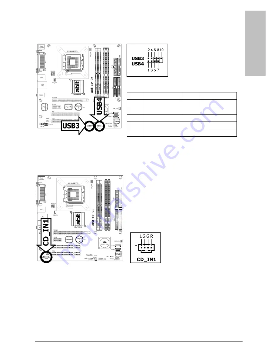
1.8.3 Additional USB 2.0 Port Headers 

Each header supports 2x additional USB 2.0 ports by connecting bracket or cable to the rear I/O 
panel or the front-mounted USB ports of your chassis. 


Pin

Pin Assignment

Pin

Pin Assignment

1 VCC 2 VCC 

3 Data0 

- 4 Data1 

5 Data0 

+ 6 Data1 

7 Ground 8 Ground 


10 

NC 


※ 

Make sure the connecting cable bears the same pin assignment. 


1.8.4 Internal Audio Connectors 

This connector connects to the audio output of internal CD-ROM drive or add-on card. 


IP-95 

1-15 

Summary of Contents for IP-95

Page 1: ...ty Multilingual QIG Appendix IP 95 Motherboard Socket 775 Intel Core 2 Duo Intel Pentium D Intel Pentium 4 Intel Celeron D Intel Celeron VIA P4M890 VT8237R Plus FSB1066 DDR2 533 or DDR 400 PCI Express 2x SATA 1 5Gb s 5 1 Channel AC97 Audio ...

Page 2: ...for direct indirect special incidental or consequential damages arising from any defect or error in this manual or product Product names appearing in this manual are for identification purpose only and trademarks and product names or brand names appearing in this document are the property of their respective owners This document contains materials protected under International Copyright Laws All r...

Page 3: ...10 1 7 1 CPU Socket 775 1 10 1 7 2 DDR2 DDR Memory Slots 1 12 1 8 Connecting Peripheral Devices 1 13 1 8 1 Floppy and IDE Disk Drive Connectors 1 13 1 8 2 Serial ATA Connectors 1 14 1 8 3 Additional USB 2 0 Port Headers 1 15 1 8 4 Internal Audio Connectors 1 15 1 8 5 Front Panel Audio Connection Header 1 16 1 8 6 PCI and PCI Express X16 X1 Slots 1 17 1 9 Connecting Rear Panel I O Devices 1 18 2 BI...

Page 4: ...iv IP 95 iv IP 95 ...

Page 5: ...er LAN Onboard 10 100M PCI controller Audio Onboard 5 1 CH AC97 Audio CODEC Serial ATA 2x SATA 1 5Gb s Expansion Slots 1x PCI E X16 slot 1x PCI E X1 slot 2x PCI slots Internal I O Connectors 1x Floppy port 2x ATA 133 IDE connectors 2x SATA 1 5Gb s connectors 2x USB 2 0 headers 1x FP Audio header 1x CD In connector Rear Panel I O 1x PS 2 Keyboard connector 1x PS 2 Mouse connector 1x COM port 1x LPT...

Page 6: ...1 2 Motherboard Layout 1 2 IP 95 ...

Page 7: ...he mounting holes on the chassis If the holes line up and there are screw holes you can attach the board with studs If the holes line up and there are only slots you can only attach with spacers Take the tip of the spacers and insert them into the slots After doing this to all the slots you can slide the board into position aligned with slots After the board has been positioned check to make sure ...

Page 8: ...lock was incorrectly set in the BIOS menu or d whenever there is modification on the CPU or memory modules This header uses a jumper cap to clear the CMOS memory and have it reconfigured to the default values stored in BIOS Pins 1 and 2 shorted Default Normal operation Pins 2 and 3 shorted Clear CMOS memory To clear the CMOS memory and load in the default values 1 Power off the system 2 Set pin 2 ...

Page 9: ... renew the backup battery 1 Power off the system and disconnect with AC power source 2 Remove the exhausted battery 3 Insert a new CR2032 or equivalent battery Pay attention to its polarity The side is its positive polarity 4 Connect AC power source and power on the system 5 Enter the BIOS setup menu Reconfigure the setup parameters if necessary CAUTION Danger of explosion may arise if the battery...

Page 10: ...24 Pin Power Connector The power supply with 20 pin or 24 pin cables can both be connected to this 24 pin connector Connect from pin 1 for either type However a 20 pin power supply may cause the system unstable or even unbootable for the sake of insufficient electricity A minimum power of 300W or higher is recommended ATX 12V 4 Pin Power Connector This connector supplies power to CPU The system wi...

Page 11: ... align to the pin in the figure below stands for positive polarity for the LED connection Please pay attention when connecting these headers A wrong orientation will only cause the LED not lighting but a wrong connection of the switches could cause system malfunction Pin Definition Pin Definition 1 HD LED 2 Message LED 3 HD LED 4 Message LED 5 RESET 6 Power Switch 7 RESET 8 Power Switch 9 Reserved...

Page 12: ...ovide power to the cooling fans installed in your system CPU_FAN CPU Fan Power Connector SYS_FAN System Fan Power Connector PWR_FAN Auxiliary Fan Power Connector These fan connectors are not jumpers DO NOT place jumper caps on these connectors 1 8 IP 95 ...

Page 13: ...Hardware Setup 1 6 4 Chassis Speaker Connector This header provides the connection to chassis speaker IP 95 1 9 ...

Page 14: ...y For detailed information on how to install the one you bought refer to its installation guidelines 1 Place the board so as to let the lever hook of the socket is on your left side Use your left thumb and forefinger to hold the lever hook pull it away from the retention tab Rotate the lever to fully open position 2 Use your right thumb to raise the load plate Lift it up to fully open position 3 U...

Page 15: ...on tab 8 Place the heatsink and fan assembly onto the socket Align the four fasteners toward the four mounting holes on the motherboard 9 Press each of the four fasteners down into the mounting holes Rotate the fastener clock wise to lock the heatsink and fan assembly into position 10 Attach the four pin power plug from the heatsink and fan assembly to the CPU FAN connector A higher fan speed will...

Page 16: ... 3 Hold two edges of the DIMM module carefully keep away from touching its connectors 4 Align the notch key on the module with the rib on the slot 5 Firmly press the module into the slots until the ejector tabs at both sides of the slot automatically snap into the mounting notch Do not force the DIMM module in with extra force as the DIMM module only fits in one direction 6 To remove the DIMM modu...

Page 17: ...h pin 1 on both the FDC1 port and the floppy connector Each of the IDE port connects up to two IDE drives at Ultra ATA 100 mode by one 40 pin 80 conductor and 3 connector Ultra ATA 66 ribbon cables Connect the single end blue connector at the longer length of ribbon cable to the IDE port of this board the other two ends gray and black connector at the shorter length of the ribbon cable to the conn...

Page 18: ... either end of the signal cable to the SATA connector on motherboard Attach the other end to SATA device 2 Attach the SATA power cable to the SATA device and connect the other end from the power supply The motherboard in this illustration is served for DEMO only may not be the same type or model as the one described in this user s manual 1 14 IP 95 ...

Page 19: ...O panel or the front mounted USB ports of your chassis Pin Pin Assignment Pin Pin Assignment 1 VCC 2 VCC 3 Data0 4 Data1 5 Data0 6 Data1 7 Ground 8 Ground 10 NC Make sure the connecting cable bears the same pin assignment 1 8 4 Internal Audio Connectors This connector connects to the audio output of internal CD ROM drive or add on card IP 95 1 15 ...

Page 20: ...le attach the jumpers back at pin 5 6 and pin 9 10 default setting Pin Signal Name Function 1 AUD_MIC Front Panel Microphone input signal 2 AUD_GND Ground used by Analog Audio Circuits 3 AUD_MIC_BIAS Microphone Power 4 AUD_VCC Filtered 5V used by Analog Audio Circuits 5 AUD_F_R Right Channel audio signal to Front Panel 6 AUD_RET_R Right Channel Audio signal to Return from Front Panel 7 REVD Reserv...

Page 21: ...are Setup 1 8 6 PCI and PCI Express X16 X1 Slots Install PCI Express X16 graphics card into slot PCIEX16 Install PCI Express X1 card into slot PCIEX1 Install PCI cards into slots PCI1 and or PCI2 IP 95 1 17 ...

Page 22: ...e or other devices that support this communication protocol VGA1 Connects to monitor input LAN1 Connects to Local Area Network USB1 USB2 Connects to USB devices such as scanner digital speakers monitor mouse keyboard hub digital camera joystick etc AUDIO1 Line In Connects to the line out from external audio sources Line Out Connects to the front left and front right channel in the 5 1 channel or r...

Page 23: ...computer chassis Only when these two methods fair should you restart the system by powering it off and then back on After pressing Del key the main menu screen appears CMOS Setup Utility Copyright C 1985 2005 American Megatrends Inc Standard CMOS Setup CPU PnP Setup Advanced Setup Hardware Monitor Features Setup Load Optimal Defaults Power Management Setup Save Changes and Exit PCI PnP and Play Se...

Page 24: ...2 2 IP 95 ...

Page 25: ...llation auto run screen appears If not browse the root directory of the CD ROM via the File Manager and double click the AUTORUN file Drivers Click to enter the driver installation menu Manual Click to enter the user s manual menu Utility Click to enter the utilities installation menu ABIT Utility Click to enter the installation menu of utilities exclusively developed by ABIT Browse CD Click to br...

Page 26: ...3 2 IP 95 3 2 IP 95 ...

Page 27: ... 條 240 針腳 DIMM 插槽 1 8V 支援 DDR2 533 記憶體最大 4GB 記憶體容量 圖形埠 整合 VIA UniChrome Pro 2D 3D 圖形與 影像控制器 網路 內建 10 100M PCI 網路控制器 音效 內建 5 1 聲道 AC97 音效 Serial ATA 2 個 SATA 1 5Gb s 擴充插槽 1 個 PCI E X16 插槽 1 個 PCI E X1 插槽 2 個 PCI 插槽 內部輸入 輸出接頭 1 個軟碟埠 2 個 ATA 133 IDE 接頭 2 個 SATA 1 5Gb s 接頭 2 個 USB 2 0 接頭 1 個 FP Audio 接頭 1 個 CD In 接頭 後面板輸入 輸出接頭 1 個 PS 2 鍵盤接頭 1 個 PS 2 滑鼠接頭 1 個 COM 連接埠 1 個 LPT 連接埠 1 個 VGA 連接埠 4 個 USB 2 0...

Page 28: ...憶體 若要清除 CMOS 記憶體 拔除主機板上所有的電源 線 將跳線連接到標有 清除 CMOS 的設定數秒鐘 然後再將跳線插回 一般 設定 插回所有電源並重 新啟動電源時 BIOS 內容將重新設定成預設值 連接機殼元件 ATX 電源供應器 ATXPWR1 ATX12V1 將標準 ATX 電源供應器連接至 2x12 針腳的 ATXPWR1 插座 將輔助電源連接至 2x2 針腳的 ATX12V1 插座 風扇插座 CPUFAN1 CPU 冷卻風扇插座 SYSFAN1 系統冷卻風扇插座 AUXFAN1 輔助冷卻風扇插座 NBFAN1 北橋冷卻風扇插座 這些風扇插座並不是跳線 請勿將跳線置於這些插座 上 前面板插座 FPIO1 HLED 連接至硬碟 LED 連接線 RST 連接至重新啟動開關連接線 SPKR 連接至系統喇叭連接線 SLED 連接至暫停 LED 連接線 PWR 連接至電源開關連接線 P...

Page 29: ...裝 CPU 和散熱片配件 由於市面上有多種中央處理器 Central Processing Unit CPU 和專用的散熱片可供選擇 而安裝方式也 各有不同 請確實遵循所購買產品包裝中隨附的安裝 指示 CPU 是一種精密的電子裝置 運作時會散發大 量的熱能 請務必小心處理 將散熱片安裝到處理器上以後 請將散熱風扇的電源 連接到主機板上的 CPUFAN1 插座 安裝記憶體模組 靜電可能會損壞電腦或選購機板的電子元件 請在開 始上述操作程序之前 先短暫觸摸接地的金屬物件 以排除靜電 連接儲存裝置 連接軟碟機 FDC1 連接 IDE 硬碟 IDE1 IDE2 連接序列 ATA 硬碟機 SATA1 SATA4 這些插座提供透過序列 ATA 連接 線 每個通道連接一台序列 ATA 裝 置 背面板線路連接 Mouse 連接 PS 2 滑鼠 Keyboard 連接 PS 2 鍵盤 LPT1 連接印表機或...

Page 30: ...4 6 IP 95 4 6 IP 95 ...

Page 31: ...DR2 533 内存最大 4GB 内存容量 图形端口 整合 VIA UniChrome Pro 2D 3D 图形与 影像控制器 网络 内建 10 100M PCI 网络控制器 音效 支持 5 1 声道 AC97 音效 串行 ATA 2 个 SATA 1 5Gb s 扩充插槽 1 个 PCI E X16 插槽 1 个 PCI E X1 插槽 2 个 PCI 插槽 内部输入 输出接头 1 个软盘端口 2 个 ATA 133 IDE 接头 2 个 SATA 1 5Gb s 接头 2 个 USB 2 0 接头 1 个 FP Audio 接头 1 个 CD In 接头 后面板输入 输出接头 1 个 PS 2 键盘接头 1 个 PS 2 鼠标接头 1 个 COM 连接埠 1 个 LPT 连接埠 1 个 VGA 连接埠 4 个 USB 2 0 接头 1 个 RJ 45 网络接头 1 个 5 1 声道音效...

Page 32: ...MOS 存储器 请断开主板上的所有电源线 将跳线帽插到 清除 CMOS 位置上几秒钟 然后将 跳线帽插回 正常 位置 重新接通所有电源并启动 后 BIOS 内容将恢复成默认配置 连接底盘元件 ATX 电源 ATXPWR1 ATX12V1 将 标 准 的 ATX 电 源 连 接 到 2x12 针 脚 的 ATXPWR1 连接器 将自备电源连接到 2x2 针脚的 ATX12V1 连接 器 风扇连接器 CPUFAN1 CPU 冷却风扇连接器 SYSFAN1 系统冷却风扇连接器 AUXFAN1 辅助冷却风扇连接器 NBFAN1 北桥冷却风扇连接器 这些风扇连接器不是跳线 不要将跳线帽插到这些连 接器上 前面板连接器 FPIO1 HLED 连接 HDD LED 电缆 RST 连接复位开关电缆 SPKR 连接系统扬声器电缆 SLED 连接挂起 LED 电缆 PWR 连接电源开关电缆 PLED 连接电源...

Page 33: ...和过热降温装置 可供选择的中央处理单元 CPU 及其过热降温装置 有很多种 每一种的安装方式都不相同 因此请严格 按照产品包装中的安装说明进行操作 CPU 是一种精 密的电子设备 工作时会产生大量热量 操作时 务 请小心谨慎 将过热降温装置安装到处理器上后 把 CPU 冷却风扇 的电源连接到主板上的 CPUFAN1 连接器 安装内存模块 静电可能会损坏计算机或板卡选件上的电子元件 在 开始上述操作之前 请触摸一下接地的金属物品 以 确保释放身上的静电 连接存储设备 连接软盘驱动器 FDC1 连接 IDE 硬盘驱动器 IDE1 IDE2 连接串行 ATA 硬盘驱动器 SATA1 SATA4 这些连接器的作用在于利用串行 ATA 电缆在每个通道上连接一个串 行 ATA 设备 后面板连接 Mouse 连接 PS 2 鼠标 Keyboard 连接 PS 2 键盘 LPT1 连接打印机或其它支持并行...

Page 34: ...4 10 IP 95 4 10 IP 95 ...

Page 35: ...methods to discharge CMOS data recover the hardware default status and then making the motherboard work again There is no need to bother returning the motherboard to where you bought it from or go through an RMA process Step 1 Switch off the power supply unit and then switch it on again after one minute If there is no power switch on the power supply unit disconnect its power cord for one minute a...

Page 36: ... resolution mixed or if a certain program cannot be executed etc you may Upgrade the motherboard s latest BIOS version Upgrade the add on device s latest driver version Check if there is any conflict in the Control Panel System Properties Q How to fill in the Technical Support Form A To fill in this Technical Support Form please refer to the following instructions Region Type in your country name ...

Page 37: ...l drives and quantity Specify if it was inserted on IDE Master or Slave or SATA ports Other devices Indicate which add on cards or USB devices that you absolutely sure are related to the problem If you cannot identify the problem s origin indicate all the add on cards or USB devices inserted on your system Example AHA 29160 on PCI 2 Sandisk Cruzer mini 256MB USB Flash disk Operating system Indicat...

Page 38: ... Name Subject Motherboard BIOS Version CPU Memory brand Memory size Memory configuration Graphics card Graphics driver version Power supply maker Power supply wattage Storage devices Optical devices Other devices Operating system Problem description 5 4 IP 95 ...

Page 39: ...1438 362088 Germany and Benelux Belgium Netherlands Luxembourg France Italy Spain Portugal Greece Denmark Norway Sweden Finland Switzerland Universal ABIT NL B V Jan van Riebeeckweg 15 5928LG Venlo The Netherlands Tel 31 77 3204428 Fax 31 77 3204420 Austria Czech Romania Bulgaria Slovakia Croatia Bosnia Serbia Macedonia Slovenia Universal ABIT Austria Computer GmbH Schmalbachstrasse 5 A 2201 Geras...

Page 40: ...P N 4310 0000 51 Rev 1 00 http www abit com tw ...

Reviews: