background image


1-4 

NF-95 

Summary of Contents for NF-95

Page 1: ...Introduction Hardware Setup BIOS Setup Driver Utility CD Appendix NF 95 Motherboard AMD Athlon 64FX 64X2 64 Sempron Socket 939 Installation Guide ...

Page 2: ...tal or consequential damages arising from any defect or error in this manual or product Product names appearing in this manual are for identification purpose only and trademarks and product names or brand names appearing in this document are the property of their respective owners This document contains materials protected under International Copyright Laws All rights reserved No part of this manu...

Page 3: ...nt Panel Audio Connection Header 2 8 2 5 Installing Hardware 2 9 2 5 1 CPU Socket 939 2 9 2 5 2 DDR Memory Slots 2 12 2 5 3 Floppy and IDE Disk Drive Connectors 2 14 2 5 4 PCI Express X16 Add on Slots 2 15 2 5 5 PCI Add on Slots 2 15 2 5 6 Serial ATA Connectors 2 16 2 6 Connecting Optional Devices 2 17 2 6 1 Additional USB 2 0 Port Headers 2 17 2 6 2 Internal Audio Connector 2 18 2 7 Connecting I ...

Page 4: ...3 19 3 11 Save Exit Setup 3 19 3 12 Exit Without Saving 3 19 4 Driver Utility CD 4 1 5 Appendix 5 1 5 1 Troubleshooting How to Get Technical Support 5 1 5 1 1 Q A 5 1 5 1 2 Technical Support Form 5 4 5 1 3 UNIVERSAL ABIT Contact Information 5 5 iv NF 95 ...

Page 5: ... DDR 400 333 Un buffered ECC memory Graphics Integrated NVIDIA GeForce 6100 controller provides enthusiast class GeForce 6 graphics features Serial ATA 2x SATA 3Gb s Supports SATA RAID 0 1 JBOD LAN Onboard 10 100Mb PCI controller Audio Onboard 5 1 Channel Audio CODEC Expansion Slots 1x PCI Express x16 slot 3x PCI slots Internal I O Connectors 1x floppy disk drive connector 2x UDMA 133 100 66 33 ID...

Page 6: ...serial port 1x parallel port 1x VGA port 4x USB 2 0 ports 1x RJ 45 LAN port Audio jacks for line in line out and microphone Miscellaneous Micro ATX form factor 224mm x 244mm Specifications and information contained herein are subject to change without notice 1 2 NF 95 ...

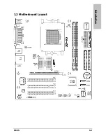
Page 7: ...Introduction 1 2 Motherboard Layout NF 95 1 3 ...

Page 8: ...1 4 NF 95 ...

Page 9: ...ves for I O shield located at the rear panel Make sure the I O shield of the chassis matches the I O port configuration of this motherboard You can find an I O shield specifically designed for this motherboard in its package 2 2 Installing Motherboard Most computer chassis have a base with many mounting holes to allow the motherboard to be securely attached and at the same time prevent the system ...

Page 10: ...ve them tightened Face the chassis s rear panel To prevent shorting the PCB circuit please REMOVE the metal studs or spacers if they are already fastened on the chassis base and are without mounting holes on the motherboard to align with 2 3 Checking Jumper Settings For a 2 pin jumper plug the jumper cap on both pins will make it CLOSE SHORT Remove the jumper cap or plug it on either pin reserved ...

Page 11: ...ed to the default values stored in the ROM BIOS Pins 1 and 2 shorted default Normal operation Pins 2 and 3 shorted Clear CMOS memory To clear the CMOS memory and load the default values 1 Power off the system 2 Set pin 2 and pin 3 shorted by the jumper cap Wait for a few seconds Set the jumper cap back to its default settings pin 1 and pin 2 shorted 3 Power on the system 4 For incorrect CPU ratio ...

Page 12: ...w the backup battery 1 Power off the system and disconnect with AC power source 2 Remove the exhausted battery 3 Insert a new CR2032 or equivalent battery Pay attention to its polarity The side is its positive polarity 4 Connect AC power source and power on the system 5 Enter the BIOS setup menu Reconfigure the setup parameters if necessary CAUTION Danger of explosion may arise if battery is incor...

Page 13: ...in Power Connector The power supply with 20 pin or 24 pin cables can both be connected to this 24 pin connector Connect from pin 1 for either type However a 20 pin power supply may cause the system unstable or even unbootable for the sake of insufficient electricity A minimum power of 300W or higher is recommended ATX 12V 4 Pin Power Connector This 4 pin 12V power connector mainly supplies power t...

Page 14: ...align to the pin in the figure below stands for positive polarity for the LED connection Please pay attention to connect these headers A wrong orientation will only cause the LED not lighting but a wrong connection of the switches could cause system malfunction Pin Definition Pin Definition 1 HD LED 2 MSG LED 3 HD LED 4 MSG LED 5 RESET 6 Power Switch 7 RESET 8 Power Switch 9 Reserved 2 6 NF 95 ...

Page 15: ...onnectors each provide power to the cooling fans installed in your system CPU_FAN CPU Fan Power Connector SYS_FAN System Fan Power Connector PWR_FAN Auxiliary Fan Power Connector These fan connectors are not jumpers DO NOT place jumper caps on these connectors ...

Page 16: ...ut signal 2 AUD_GND Ground used by Analog Audio Circuits 3 AUD_MIC_BIAS Microphone Power 4 AUD_VCC Filtered 5V used by Analog Audio Circuits 5 AUD_F_R Right Channel audio signal to Front Panel 6 AUD_RET_R Right Channel Audio signal to Return from Front Panel 7 REVD Reserved 8 Key No Pin 9 AUD_F_L Left Channel Audio signal to Front Panel 10 AUD_RET_L Left Channel Audio signal to Return from Front P...

Page 17: ... the socket lever away from the socket and fully lift it up over 90 degree angle 2 Locate and align the triangle mark with both the CPU and the socket body Vertically place the CPU with its pin side down into the socket Be careful to insert the CPU into the socket The CPU only fits in one orientation with the socket DO NOT force the CPU into the socket 3 After placing the CPU into position push th...

Page 18: ...assembly onto the retention frame Match the heatsink clip with the socket mounting lug Hook the spring clip to the mounting lug Put the CPU Fan down on the retention module and snap the four retention legs of the cooling fan into place 6 On the other side push the retention clip straight down to lock into the plastic lug on the retention frame 7 Flip the lever over to lock the heat sink in place 2...

Page 19: ... CPU fan and heatsink assembly The one shown here is served for demo only For detailed information on how to install the one you bought refer to its installation guidelines A higher fan speed will be helpful for better airflow and heat dissipation Nevertheless stay alert to touch any heatsink since the high temperature generated by the working system is still possible ...

Page 20: ...r AMD 939 pin Processor Chip Selects Maximum DRAM Speed Data Bus DIMM1 DIMM2 1T 2T Single Rank N A DDR400 DDR400 64 bits Single Channel Double Rank N A DDR400 DDR400 Single Rank Single Rank DDR400 DDR400 128 bits Dual Channel Double Rank Double Rank DDR400 DDR400 To reach the optimum performance in dual channel configurations install DDR DIMM pairs at the same density DRAM technology and bus width...

Page 21: ...odule into the slots until the ejector tabs at both sides of the slot automatically snaps into the mounting notch Do not force the DIMM module in with extra force as the DIMM module only fit in one direction 6 To remove the DIMM modules push the two ejector tabs on the slot outward simultaneously and then pull out the DIMM module Static electricity can damage the electronic components of the compu...

Page 22: ...ort and the floppy connector Each of the IDE port connects up to two IDE drives at Ultra ATA 100 mode by one 40 pin 80 conductor and 3 connector Ultra ATA 66 ribbon cables Connect the single end blue connector at the longer length of ribbon cable to the IDE port of this board the other two ends gray and black connector at the shorter length of the ribbon cable to the connectors of your hard drives...

Page 23: ...PCI Express X16 Add on Slots This slot supports the connection of graphics card that comply with PCI Express specifications 2 5 5 PCI Add on Slots These slots provide the connection of add on cards that comply with PCI specifications ...

Page 24: ...he item On Chip SATA Controller and its sub item RAID Mode in the IDE Function Setup BIOS menu has to be set to Enabled first SATA power cable optional SATA signal cable optional To connect SATA device 1 Attach either end of the signal cable to the SATA connector on motherboard Attach the other end to SATA device 2 Attach the SATA power cable to the SATA device and connect the other end from the p...

Page 25: ... also features 2x more USB 2 0 headers onboard Each header supports 2x additional USB 2 0 ports by connecting bracket or cable to the rear I O panel or the front mounted USB ports of your chassis Pin Pin Assignment Pin Pin Assignment 1 VCC 2 VCC 3 Data0 4 Data1 5 Data0 6 Data1 7 Ground 8 Ground 9 NC 10 NC Make sure the connecting cable bears the same pin assignment ...

Page 26: ...2 6 2 Internal Audio Connector These connectors connect to the audio output of internal CD ROM drive or add on card 2 18 NF 95 ...

Page 27: ...t support this communication protocol VGA1 Connects to monitor input LAN1 Connects to Local Area Network USB1 USB2 Connects to USB devices such as scanner digital speakers monitor mouse keyboard hub digital camera joystick etc AUDIO Line In Connects to the line out from external audio sources Line Out Connects to the front left and front right channel in the 5 1 channel or regular 2 channel audio ...

Page 28: ...2 20 NF 95 ...

Page 29: ...n the memory count begins and then the following message appears on the screen PRESS DEL TO ENTER SETUP If this message disappears before you respond restart the system by pressing Ctrl Alt Del keys or by pressing the Reset button on computer chassis Only when it failed by these two methods can you restart the system by powering it off and then back on After pressing Del key the main menu screen a...

Page 30: ...fy usually the current time in the format of Hour Minute and Second IDE Channel 1 Master Slave IDE Channel 2 Master Slave IDE Channel 3 Master IDE Channel 4 Master Click Enter key to enter its submenu The items IDE Channel 3 Master and IDE Channel 4 Master appear only when the item On Chip SATA Controller in the IDE Function Setup menu is set to the default Enabled parameter 3 2 NF 95 ...

Page 31: ... HDD automatically Capacity This item displays the approximate capacity of the disk drive Usually the size is slightly greater than the size of a formatted disk given by a disk checking program Cylinder This item configures the numbers of cylinders Head This item configures the numbers of read write heads Precomp This item displays the number of cylinders at which to change the write timing Landin...

Page 32: ...tte The system boot will stop for all errors except a diskette error All But Disk Key The system boot will stop for all errors except a diskette or keyboard error Base Memory This item displays the amount of base memory installed in the system The value of the base memory is typically 640K for system with 640K or more memory size installed on the motherboard Extended Memory This item displays the ...

Page 33: ...t Device Boot Other Device Select the drive to boot first second and third in the First Boot Device Second Boot Device and Third Boot Device items respectively The BIOS will boot the operating system according to the sequence of the drive selected Set Boot Other Device to Enabled if you wish to boot from another device other than these three items Boot Up Floppy Seek When set to Enabled the BIOS w...

Page 34: ...o open the computer case and clear all information in the CMOS before you can start up the system But by doing this you will have to reset all previously set options Delay For HDD Secs This item allows the BIOS to support some old or special IDE devices by prolonging this delay time A larger value will give more delay time to the device for which to initialize and to prepare for activation 3 6 NF ...

Page 35: ... K8 NB HT Speed This item sets the speed of HyperTransport between CPU and Northbridge NB SB HT Speed This item sets the speed of HyperTransport from Northbridge to Southbridge NB SB HT Speed This item sets the speed of HyperTransport from Southbridge to Northbridge K8 NB HT Width This item sets the HyperTransport width between CPU and Northbridge NB SB HT Width This item sets the HyperTransport w...

Page 36: ...er of DRAM clocks used for the DRAM parameters CAS Latency Time This item controls the latency between the DRAM read command and the time that the data becomes actually available Min RAS Active Time This item specifies the minimum RAS active time RAS to CAS Delay This item controls the latency between the DRAM active command and the read write command RAS Precharge Time This item controls the idle...

Page 37: ...BIOS Setup NF 95 3 9 Async Latency value This item manually specifies the DRAM asynchronous latency value ...

Page 38: ...ontroller This item selects whether to enable or disable the SATA controller RAID Mode This item selects whether to enable or disable the RAID controller IDE Prefetch Mode The onboard IDE drive interfaces supports IDE prefetching for faster drive accesses If you install a primary and or secondary add in IDE interface set this field to Disabled if the interface does not support prefetching 3 10 NF ...

Page 39: ...d On Chip USB Controller This option enables or disables the USB controller USB Keyboard Support via Select BIOS the default setting for the legacy operating system such as DOS that does not support USB keyboard USB Mouse Support via Select BIOS the default setting for the legacy operating system such as DOS that does not support USB mouse On Chip Audio Controller This option enables or disables t...

Page 40: ...cessing any system resources When the value of this option is set to Disabled the printer port becomes unavailable 378 IRQ7 This option allows the parallel port to use 378 IRQ7 as its I O port address The majority of parallel ports on computer systems use IRQ7 and I O Port 378H as the standard setting 278 IRQ5 This option allows the parallel port to use 278 IRQ5 as its I O port address 3BC IRQ7 Th...

Page 41: ...aster than the normal mode s data transfer rate ECP EPP Allows parallel port operation at ECP and EPP mode EPP Mode Select This item selects the EPP mode ECP Mode Use DMA This item selects the DMA channel of the parallel port ...

Page 42: ...m This will prevent the system from powering off in case you accidentally hit or pushed the power button Instant Off Pressing and then releasing the power button at once will immediately power off the system Power On Function This item selects the way you want your system to power on Password Use a password to power on the system select this option then press Enter Enter your password You can ente...

Page 43: ...r button to power on the system Power On When power returns after an AC power failure the system s power will be powered on automatically Last State When power returns after an AC power failure the system will return to the state where you left off before power failure occurs If the system s power is off when AC power failure occurs it will remain off when power returns If the system s power is on...

Page 44: ... power on on the date set and the time set in the Time hh mm ss Alarm item Time hh mm ss Alarm This item sets the time you would like the system to power on AMD K8 Cool n Quiet Control This item helps the system to lower the frequency when CPU idles The temperature will drop automatically when the frequency decreases Leave this item to its default Auto setting and install the Cool n Quiet driver 3...

Page 45: ...u IRQ Resources Click Enter key to enter its submenu This item sets each system interrupt to either PCI Device or Reserved Back to PnP PCI Configurations Setup Menu PCI VGA Palette Snoop This item determines whether the MPEG ISA VESA VGA cards can work with PCI VGA or not Enabled MPEG ISA VESA VGA cards work with PCI VGA Disabled MPEG ISA VESA VGA cards do not work with PCI VGA Maximum Payload Siz...

Page 46: ...U and SYS fan headers up to their full speed Shutdown Temperature This item determines the temperature threshold to shut down system All Voltages Fans Speed and Thermal Monitoring These unchangeable items list the current status of the CPU and environment temperatures fan speeds and system power voltage 3 18 NF 95 ...

Page 47: ...option loads the BIOS default values that are factory settings for optimal performance system operations 3 10 Set Password This option protects the BIOS configuration or restricts access to the computer itself 3 11 Save Exit Setup This option saves your selections and exits the BIOS setup menu 3 12 Exit Without Saving This option exits the BIOS setup menu without saving any changes ...

Page 48: ...3 20 NF 95 ...

Page 49: ...rectory of the CD ROM via the File Manager and double click the AUTORUN file Drivers Click on this tab to enter the menu of drivers utilities installation Manual Click on this tab to enter the menu of viewing the user s manual in PDF format Utility Click on this tab to enter the menu for installing utilities ABIT Utility Click on this tab to enter the menu for installing utilities exclusively deve...

Page 50: ...4 2 NF 95 ...

Page 51: ...e changed from default to over clocking or non standard status We suggest the following three troubleshooting methods to discharge CMOS data recover the hardware default status and then making the motherboard work again There is no need to bother returning the motherboard to where you bought it from or go through an RMA process Step 1 Switch off the power supply unit and then switch it on again af...

Page 52: ...and devices that were previously installed in the system Re install and start the system one at a time until the system won t start Malfunction in the OS If the system hangs after resuming from S3 or some testing program if the CPU cannot be recognized properly if the display resolution mixed or if a certain program cannot be executed etc you may Upgrade the motherboard s latest BIOS version Upgra...

Page 53: ...ondMax 10 SATA 300GB on SATA 3 Example 2 Maxtor DiamondMax 10 SATA 300GB 2 on SATA 3 SATA 4 RAID 1 Optical devices Type in the brand and specifications of your optical drives and quantity Specify if it was inserted on IDE Master or Slave or SATA ports Other devices Indicate which add on cards or USB devices that you absolutely sure are related to the problem If you cannot identify the problem s or...

Page 54: ...me Last Name Subject Motherboard BIOS Version CPU Memory brand Memory size Memory configuration Graphics card Graphics driver version Power supply maker Power supply wattage Storage devices Optical devices Other devices Operating system Problem description ...

Page 55: ...ia Czech Romania Bulgaria Slovakia Croatia Bosnia Serbia Macedonia Asguard Computer Ges m b H Schmalbachstrasse 5 A 2201 Gerasdorf Wien Austria Tel 43 1 7346709 Fax 43 1 7346713 Germany and Benelux Belgium Netherlands Luxembourg France Italy Spain Portugal Greece Denmark Norway Sweden Finland Switzerland AMOR Computer B V ABIT s European Office Jan van Riebeeckweg 15 5928LG Venlo The Netherlands T...

Page 56: ...Rev 2 00 http www abit com tw ...

Reviews: