8
NF-M2P/NF-M2S/NF-M2SV
1.6 Connecting Chassis Components
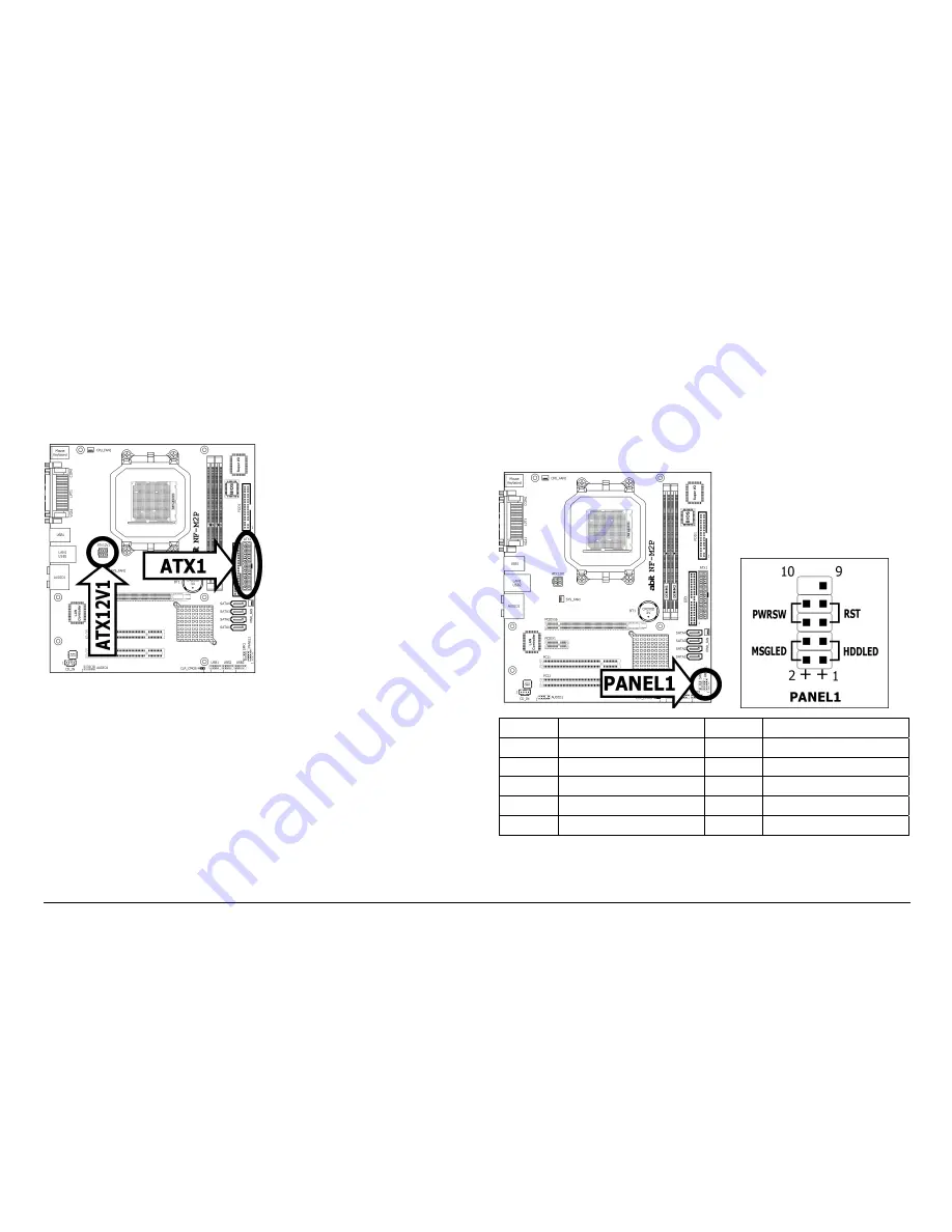
1.6.1 ATX Power Connectors
These connectors provide the connection from an ATX power supply. As
the plugs from the power supply fit in only one orientation, find the
correct one and push firmly down into these connectors.
ATX 24-Pin Power Connector:
The power supply with 20-pin or 24-pin cables can both be connected
to this 24-pin connector. Connect from pin-1 for either type. However, a
20-pin power supply may cause the system unstable or even
unbootable for the sake of insufficient electricity. A minimum power of
300W or higher is recommended.
ATX 12V 4-Pin Power Connector:
This connector supplies power to CPU. The system will not start without
connecting power to this one.
1.6.2 Front Panel Switches and Indicators Headers
This header is used for connecting switches and LED indicators on the
chassis front panel.
Watch the power LED pin position and orientation. The mark “+” align
to the pin in the figure below stands for positive polarity for the LED
connection. Please pay attention when connecting these headers. A
wrong orientation will only result in the LED not lighting, but a wrong
connection of the switches could cause system malfunction.
Pin Definition Pin Definition
1
HD LED +
2
Message LED +
3
HD LED -
4
Message LED -
5 RESET 6
Power
Switch
7 RESET 8
Power
Switch
9 Reserved


