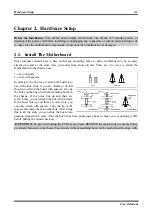
background image

2-12 

Chapter 2 

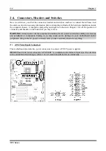
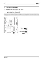
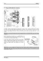
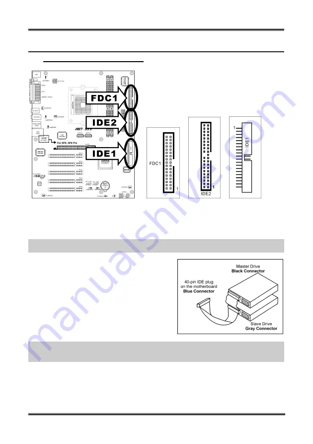
(11). Floppy and IDE Disk Drive Connectors 


The FDC1 connector connects up to two floppy drives with a 34-wire, 2-connector floppy cable. Connect 
the single end at the longer length of ribbon cable to the FDC1 on the board, the two connectors on the 
other end to the floppy disk drives connector. Generally you need only one floppy disk drive in your 
system. 

NOTE:

 The red line on the ribbon cable must be aligned with pin-1 on both the FDC1 port and the floppy 

connector. 

Each of the IDE port connects up to two IDE drives at 
Ultra ATA/100 mode by one 40-pin, 80-conductor, and 
3-connector Ultra ATA/66 ribbon cables. 

Connect the single end (blue connector) at the longer 
length of ribbon cable to the IDE port of this board, the 
other two ends (gray and black connector) at the shorter 
length of the ribbon cable to the connectors of your hard 
drives. 

NOTE:

 Make sure to configure the “Master” and “Slave” relation before connecting two drives by one 

single ribbon cable. The red line on the ribbon cable must be aligned with pin-1 on both the IDE port and 
the hard-drive connector. 

NF8 Series 

Summary of Contents for NF8 Series

Page 1: ...NF8 Series NF8 Pro NF8 NF8 V Pro NF8 V Socket 754 System Board User s Manual 4200 0432 04 Rev 1 01 ...

Page 2: ...al or consequential damages arising from any defect or error in this manual or product Product names appearing in this manual are for identification purpose only and trademarks and product names or brand names appearing in this document are the property of their respective owners This document contains materials protected under International Copyright Laws All rights reserved No part of this manua...

Page 3: ...B Port Headers 2 8 6 Additional IEEE1394 Port Headers NF8 Pro NF8 2 8 7 Wake up Header 2 9 8 Front Panel Audio Connection Header 2 10 9 Internal Audio Connectors 2 11 10 Accelerated Graphics Port Slot 2 11 11 Floppy and IDE Disk Drive Connectors 2 12 12 Serial ATA Connectors 2 13 13 Status Indicators 2 13 14 Back Panel Connectors 2 14 Chapter 3 BIOS Setup 3 1 3 1 SoftMenu Setup 3 2 3 2 Standard CM...

Page 4: ...1 Appendix B Install Realtek Audio Driver B 1 Appendix C Install USB 2 0 Driver C 1 Appendix D Install AMD64 Processor Driver D 1 Appendix E ABIT EQ The Hardware Doctor Utility E 1 Appendix F FlashMenu BIOS Update Utility F 1 Appendix G NF8 NVRaid Floppy Disk G 1 Appendix H Troubleshooting Need Assistance H 1 Appendix I How to Get Technical Support I 1 NF8 Series ...

Page 5: ...un buffered memory Supports maximum memory capacity up to 2GB 4 ABIT Engineered ABIT SoftMenu Technology ABIT CPU ThermalGuard Technology 5 SATA NV RAID Serial ATA 1 5Gbps data transfer rate Supports SATA RAID 0 1 JBOD 6 GbE LAN NVIDIA Gigabit Ethernet Controller 7 IEEE 1394 NF8 Pro NF8 Supports 2 Ports IEEE 1394 at 100 200 400 Mb s transfer rate 8 Audio Onboard 6 channel Audio CODEC Supports auto...

Page 6: ... 1x AUDIO1 connector Rear Left Rear Right Center Subwoofer 1x AUDIO2 connector Mic In Line In Front Left Front Right 4x USB 2 0 1x RJ 45 LAN Connector 1x IEEE 1394 Connector NF8 Pro NF8 11 Miscellaneous ATX form factor 305 x 245 mm 12 Order Information Model Features NF8 Pro IEEE 1394 S P DIF In Out NF8 IEEE1394 NF8 V Pro S P DIF In Out NF8 V Specifications and information contained herein are sub...

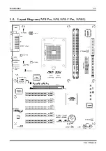
Page 7: ...Introduction 1 3 1 2 Layout Diagram NF8 Pro NF8 NF8 V Pro NF8 V User s Manual ...

Page 8: ...1 4 Chapter 1 1 4 Chapter 1 NF8 Series NF8 Series ...

Page 9: ...he best way to attach the board is to use with studs Only if you are unable to do this should you attach the board with spacers Line up the holes on the board with the mounting holes on the chassis If the holes line up and there are screw holes you can attach the board with studs If the holes line up and there are only slots you can only attach with spacers Take the tip of the spacers and insert t...

Page 10: ...p the processor with its pin side down into the CPU socket Do not use extra force to insert CPU it only fits in one direction Close the CPU release lever 3 Align the Backplate Standoffs with the mounting holes on motherboard Position the backplate onto motherboard 4 Place the Retention Frame onto the motherboard and align it with the Backplate Standoffs 5 Place heatsink on top of CPU and make sure...

Page 11: ... modules 1 Locate the DIMM slot on the board 2 Hold two edges of the DIMM module carefully keep away of touching its connectors 3 Align the notch key on the module with the rib on the slot 4 Firmly press the module into the slots until the ejector tabs at both sides of the slot automatically snaps into the mounting notch Do not force the DIMM module in with extra force as the DIMM module only fit ...

Page 12: ...board that you may refer to WARNING Always power off the computer and unplug the AC power cord before adding or removing any peripheral or component Failing to so may cause severe damage to your motherboard and or peripherals Plug in the AC power cord only after you have carefully checked everything ATX Power Input Connectors 1 This motherboard provides two power connectors to connect ATX12V power...

Page 13: ...ower to the cooling fans installed in your system CPUFAN1 CPU Fan Power Connector SYSFAN1 System Fan Power Connector AUXFAN1 AUXFAN2 PWRFAN1 Auxiliary Fan Power Connector WARNING These fan connectors are not jumpers DO NOT place jumper caps on these connectors User s Manual ...

Page 14: ... clear the CMOS memory Pin 1 2 shorted default Normal operation Pin 2 3 shorted Clear CMOS memory WARNING Turn the power off first including the 5V standby power before clearing the CMOS memory Failing to do so may cause your system to work abnormally or malfunction NF8 Series ...

Page 15: ...ation will only cause the LED not lighting but a wrong connection of the switches could cause system malfunction HLED Pin 1 3 Connects to the HDD LED cable of chassis front panel RST Pin 5 7 Connects to the Reset Switch cable of chassis front panel SPKR Pin 13 15 17 19 Connects to the System Speaker cable of chassis SLED Pin 2 4 Connects to the Suspend LED cable if there is one of chassis front pa...

Page 16: ...in Pin Assignment Pin Pin Assignment 1 VCC 2 VCC 3 Data0 4 Data1 5 Data0 6 Data1 7 Ground 8 Ground 9 NC 10 NC Additional IEEE1394 Port Headers NF8 Pro NF8 6 This header provides one additional IEEE1394 port connection through an extension cable and bracket Pin Pin Assignment Pin Pin Assignment 1 TPA0 2 TPA0 3 GND 4 GND 5 TPB0 6 TPB0 7 12V 8 12V 9 NC 10 GND NF8 Series ...

Page 17: ...at USB1 port Pin 2 3 shorted default Enable wake up function support at USB1 port USBPWR2 Pin 1 2 shorted Disable wake up function support at USB2 port Pin 2 3 shorted default Enable wake up function support at USB2 port USBPWR3 Pin 1 2 shorted Disable wake up function support at FP USB1 port Pin 2 3 shorted default Enable wake up function support at FP USB1 port USBPWR4 Pin 1 2 shorted Disable wa...

Page 18: ... front panel by the extension cable provided with the chassis To use the audio connector at rear panel disconnect the extension cable attach the jumpers back at pin 5 6 and pin 9 10 default setting Pin Pin Assignment Pin Pin Assignment 1 Audio Mic 2 Ground 3 Audio Mic Bias 4 VCC 5 Speaker Out Right Channel 6 Speaker Out Right Channel Return 7 X 8 NC 9 Speaker Out Left Channel 10 Speaker Out Left C...

Page 19: ...cts to the audio output of internal CD ROM drive or add on card 10 Accelerated Graphics Port Slot This slot supports an optional AGP graphics card up to AGP 8X mode ATTENTION This motherboard does not support 3 3V AGP cards Use only 1 5V or 0 8V AGP cards User s Manual ...

Page 20: ... FDC1 port and the floppy connector Each of the IDE port connects up to two IDE drives at Ultra ATA 100 mode by one 40 pin 80 conductor and 3 connector Ultra ATA 66 ribbon cables Connect the single end blue connector at the longer length of ribbon cable to the IDE port of this board the other two ends gray and black connector at the shorter length of the ribbon cable to the connectors of your hard...

Page 21: ...tors are provided to attach one Serial ATA device at each channel via Serial ATA cable 13 Status Indicators LED1 5VSB This LED lights up when the power supply is connected with power source LED2 VCC This LED lights up when the system power is on User s Manual ...

Page 22: ...F8 Pro NF8 V Pro AUDIO1 R L R R Rear Left Rear Right Connects to the rear left and rear right channel in the 5 1 channel audio system Cen Sub Center Subwoofer Connects to the center and subwoofer channel in the 5 1 channel audio system AUDIO2 Mic In Connects to the plug from external microphone Line In Connects to the line out from external audio sources F L F R Front Left Front Right Connects to ...

Page 23: ...ssis Only when it failed by these two methods can you restart the system by powering it off and then back on After pressing Del key the main menu screen appears NOTE In order to increase system stability and performance our engineering staffs are constantly improving the BIOS menu The BIOS setup screens and descriptions illustrated in this manual are for your reference only may not completely matc...

Page 24: ...PU damage Setting the working frequency higher than the PCI chipset or processor specs may cause abnormal memory module functioning system hangs hard disk drive data lose abnormal functioning of the VGA card or abnormal functioning with other add on cards Using non specification settings for your CPU is not the intention of this explanation These should be used for engineering testing not for norm...

Page 25: ...ot correct The option User Define enables you to select the following voltages manually CPU Core Voltage This item selects the CPU core voltage DDR RAM Voltage This item selects the voltage for DRAM slot DDR Ref Voltage This item selects the reference voltage needed for DRAM slot to increase its conformity AGP Voltage This item selects the voltage for AGP slot nForce3 Voltage This item selects the...

Page 26: ...the format of Month Date and Year Time hh mm ss This item sets the time you specify usually the current time in the format of Hour Minute and Second IDE Channel 0 Master Slave IDE Channel 1 Master Slave IDE Channel 2 Master IDE Channel 3 Master Click Enter key to enter its submenu IDE HDD Auto Detection This item allows you to detect the parameters of IDE drives by pressing Enter key The parameter...

Page 27: ...matted disk given by a disk checking program Cylinder This item configures the numbers of cylinders Head This item configures the numbers of read write heads Precomp This item displays the number of cylinders at which to change the write timing Landing Zone This item displays the number of cylinders specified as the landing zone for the read write heads Sector This item configures the numbers of s...

Page 28: ...t Diskette The system boot will stop for all errors except a diskette error All But Disk Key The system boot will stop for all errors except a diskette or keyboard error Base Memory This item displays the amount of base memory installed in the system The value of the base memory is typically 640K for system with 640K or more memory size installed on the motherboard Extended Memory This item displa...

Page 29: ...Second Boot Device Third Boot Device Boot Other Device Select the drive to boot first second and third in the First Boot Device Second Boot Device and Third Boot Device items respectively The BIOS will boot the operating system according to the sequence of the drive selected Set Boot Other Device to Enabled if you wish to boot from another device other than these three items Boot Up Floppy Seek Wh...

Page 30: ...word If you forget the password you will have to open the computer case and clear all information in the CMOS before you can start up the system But by doing this you will have to reset all previously set options MPS Version Ctrl For OS This item specifies which version of MPS Multi Processor Specification this motherboard will use Leave this item to its default setting OS Select For DRAM 64MB Thi...

Page 31: ...requency This item selects the LDT Bus Frequency DRAM Configuration Click Enter key to enter its submenu Max Memclock Mhz This item selects the maximum memory clock limit 1T 2T Memory Timing Leave this item to its default Auto setting CAS latency Tcl Leave this item to its default Auto setting User s Manual ...

Page 32: ...our graphics card supports the mode you select Leave this item to its default Auto setting AGP Fast Write Leave this item to its default Auto setting AGP Sideband Address Leave this item to its default Auto setting Special I O for PCI Card This item allows you to assign specific I O address for add on PCI card Base I O Address This item assigns the specific I O address for the PCI card I O Length ...

Page 33: ...BIOS Setup 3 11 3 5 Integrated Peripherals OnChip IDE Device Click Enter key to enter its submenu IDE Function Setup Click Enter key to enter its submenu User s Manual ...

Page 34: ...MA mode for devices connected through IDE channels OnChip SATA Controller This item enables or disables the on chip SATA controller SATA DMA transfer This item selects the DMA mode for devices connected through SATA channels RAID Config Click Enter key to enter its submenu IDE RAID This item allows you to enable or disable the IDE RAID function IDE Channel 0 1 Master Slave RAID SATA Primary Second...

Page 35: ...led and Disabled The default setting is Enabled You can enable or disable the onboard FDD controller Onboard Serial Port 1 This is used to specify the I O address and IRQ of Serial Port 1 Six options are available Disabled 3F8 IRQ4 2F8 IRQ3 3E8 IRQ4 2E8 IRQ3 AUTO The default setting is 3F8 IRQ4 Onboard Parallel Port Sets the I O address and IRQ of the onboard parallel port Four options are availab...

Page 36: ...wer failure Power Off When power returns after an AC power failure the system s power remains off You must press the Power button to power on the system Power On When power returns after an AC power failure the system s power will be powered on automatically Former Sts When power returns after an AC power failure the system will return to the state where you left off before power failure occurs If...

Page 37: ...n on your computer power Hot Key Power On Fifteen options are available Ctrl F1 Ctrl F12 Power Wake and Any Key The default setting is Ctrl F1 You can choose the hot key that you want it to turn on your computer power Wakeup by PME of PCI Two options are available Disabled or Enabled The default setting is Disabled When set to Enabled any event affecting from PCI card PME will awaken a system that...

Page 38: ...3 16 Chapter 3 Day of Month Alarm Time hh mm ss Alarm You can set the Date month Alarm and Time Alarm hh mm ss Any event occurring will awaken a system that has powered down NF8 Series ...

Page 39: ... enter its submenu This item sets each system interrupt to either PCI Device or Reserved Back to PnP PCI Configurations Setup Menu PCI VGA Palette Snoop This item determines whether the MPEG ISA VESA VGA cards can work with PCI VGA or not Disabled MPEG ISA VESA VGA cards do not work with PCI VGA Enabled MPEG ISA VESA VGA cards work with PCI VGA PIRQ_0 Use IRQ No PIRQ 7 Use IRQ No This item specifi...

Page 40: ... shutdown to protect the processor not overheat CPU Warning Temperature This item lets you select the temperature at which you want the system to send out a warning message to the PC speakers of when the temperature goes beyond either limit You can select the temperatures you want All Voltages Fans Speed and Thermal Monitoring These unchangeable items list the current status of the CPU and environ...

Page 41: ...ads the BIOS default values that are factory settings for optimal performance system operations 3 11 Set Password This option protects the BIOS configuration or restricts access to the computer itself 3 12 Save Exit Setup This option saves your selections and exits the BIOS setup menu 3 13 Exit Without Saving This option exits the BIOS setup menu without saving any change User s Manual ...

Page 42: ...3 20 Chapter 3 NF8 Series ...

Page 43: ...g system For other operating systems please follow the on screen instructions Insert the Driver Utility CD into the CD ROM drive It should execute the installation program automatically If not double click the executable file at the main directory of this CD to enter the installation menu After entering the installation menu move your curser to Drivers tab Click nVidia nForce Chipset Driver The fo...

Page 44: ...A 2 Appendix A 6 Click Next 7 Click Next 8 Click Next 9 Click Yes 10 Click Yes 11 Choose Yes I want to restart my computer now and click Finish to complete setup NF8 Series ...

Page 45: ...nsert the Driver Utility CD into CD ROM drive it should execute the installation program automatically If not double click the execution file at the main directory of this CD to enter the installation menu After entering the installation menu move your curser to Drivers tab Click Realtek Audio Driver The following screen appears 1 Click Next 2 Choose Yes I want to restart my computer now and click...

Page 46: ...B 2 Appendix B B 2 Appendix B NF8 Series NF8 Series ...

Page 47: ... Driver C 1 Appendix C Install USB 2 0 Driver NOTE The installation for USB 2 0 driver for Windows XP or Windows 2000 is currently available by updating the latest Service Pack from Microsoft s web site User s Manual ...

Page 48: ...C 2 Appendix C C 2 Appendix C NF8 Series NF8 Series ...

Page 49: ...ation program automatically If not double click the execution file at the main directory of this CD to enter the installation menu After entering the installation menu move your curser to Drivers tab Click AMD64 Processor Driver The following screen appears NOTE For Windows 2000 operating system this AMD64 Processor Driver button will be replaced by AMD Cool n Quiet Software 1 Click OK 2 Click Nex...

Page 50: ...rom the control panel and choose the power scheme Minimal Power Management to enable Cool n Quiet NOTE For Windows 2000 or ME system an AMD Cool n Quiet tab will appear under Power Options when the Cool n Quiet software for Windows 2000 and ME is installed This must be set to Automatic Mode for Cool n Quiet to be enabled NF8 Series ...

Page 51: ...llation procedures and screen shots in this section are based on the Windows XP operating system For other operating systems please follow the on screen instructions Insert the Driver Utility CD into the CD ROM drive It should execute the installation program automatically If not double click the executable file at the main directory of this CD to enter the installation menu After entering the ins...

Page 52: ...y computer now and click Finish to complete setup 5 Execute the ABIT EQ by entering the Windows Menu Start All Programs ABIT ABIT EQ 6 This screen appears ABIT EQ shows you the status of Voltage Fan Speed and Temperature readings as well NF8 Series ...

Page 53: ... this section are based on the Windows XP operating system For other operating systems please follow the on screen instructions Insert the Driver Utility CD into the CD ROM drive It should execute the installation program automatically If not double click the executable file at the main directory of this CD to enter the installation menu After entering the installation menu move your curser to ABI...

Page 54: ...lashMenu by entering the Windows Menu Start All Programs ABIT FlashMenu 6 This FlashMenu screen appears You can easily update the BIOS from clicking Update From File One Click LiveUpdate or LiveUpdate Step by Step button NF8 Series ...

Page 55: ... other OS please follow its on screen instruction Insert the Driver Utility CD into CD ROM drive it should execute the installation program automatically If not double click the execution file at the main directory of this CD to enter the installation menu After entering the installation menu move your curser to ABIT Utility tab Click NF8 NVRaid Floppy Disk The following screen appears 1 Insert on...

Page 56: ...G 2 Appendix G G 2 Appendix G NF8 Series NF8 Series ...

Page 57: ...st the following three troubleshooting methods to discharge CMOS data recover the hardware default status and then making the motherboard work again There is no need to bother returning the motherboard to where you bought it from or go through an RMA process Step 1 Switch off the power supply unit and then switch it on again after one minute If there is no power switch on the power supply unit dis...

Page 58: ...h time you insert a card until the system will not start Keep the VGA card and the interface card that caused the problem inserted on the motherboard remove any other cards or peripheral and start again If you still cannot start note the information related to both cards in the add on Card space provided and don t forget to indicate the motherboard model version BIOS identification number CPU refe...

Page 59: ... Master Example In the HDD space check the box in the Brand space write Seagate in the Specifications space write ST31621A 1 6GB 8 CD ROM Drive Indicate the brand and specifications of your CD ROM drive Specify if it uses IDE1 or IDE2 and check in case you give no indication we will consider that your CD ROM is IDE2 Master Example In the CD ROM drive space check the box in the Brand space write Mi...

Page 60: ...me Phone Number Contact Person Fax Number E mail Address Model BIOS ID Motherboard Model No DRIVER REV OS Application Hardware Name Brand Specifications CPU HDD IDE1 IDE2 CD ROM Drive IDE1 IDE2 System Memory ADD ON CARD Problem Description NF8 Series ...

Page 61: ...ts have the best quality and compatibility In case you need service or technical support please understand the constraint we have and always check with the reseller who sold the product to you first To expedite service we recommend that you follow the procedures outlined below before contacting us With your help we can meet our commitment to provide the best service to the greatest number of ABIT ...

Page 62: ...tegrated and sold the system to you They should know best what your system configuration is and your problem They should have reasonable return or refund policies How they serve you is also a good reference for your next purchase 6 Contacting ABIT If you feel that you need to contact ABIT directly you can send email to the ABIT technical support department First please contact the support team for...

Page 63: ...any and Benelux Belgium Netherlands Luxembourg France Italy Spain Portugal Greece Denmark Norway Sweden Finland and Switzerland AMOR Computer B V ABIT s European Office Jan van Riebeeckweg 15 5928LG Venlo The Netherlands Tel 31 77 3204428 Fax 31 77 3204420 Sales sales abit nl Web Site http www abit nl Austria Czech Romania Bulgaria Slovakia Croatia Bosnia Serbia and Macedonia Asguard Computer Ges ...

Page 64: ...ently it is likely that you have a defective component Please contact the reseller from whom you bought the product You should be able to get RMA service there 8 Reporting Compatibility Problems to ABIT Because of tremendous number of email messages we receive every day we are forced to give greater weight to certain types of messages than to others For this reason any compatibility problem that i...

Reviews: