


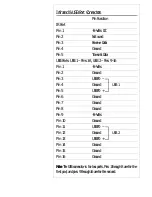


Enclosure Features Connector Block
Feature
Pin Function
Hardware Reset Connector
Pin 1
Ground
Pin 2
Reset signal
Suspend Switch Connector
Pin 6
Ground
Pin 7
Suspend
Turbo LED Connector
Pin 8
– Negative (anode) pin
Pin 9
+ Positive (cathode) pin
Speaker Connector
Pin 11
+5-Volts DC
Pin 12
Ground
Pin 13
Ground
Pin 14
Sound signal
Keylock & Power LED Connector
Pin 16
Ground
Pin 17
Keyboard inhibit signal
Pin 18
Ground
Pin 19
Unused
Pin 20
+5-Volts DC (for Power LED)
N o te :
Pins 3,4, 5, 10, 15 are unused
☞
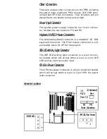
Enclosure Features Connectors
Not every pin in the connector block for
system case features is used. Which
features are used depends on the spe-
cific case design. If your case does not
have a Keyboard Lock, you can still con-
nect a Power LED lead to Pin 20 and
either Pin 16 or 18. Refer to the chart
at right for the pin assignments.
Summary of Contents for PR5
Page 10: ...System Block Diagram ...


