


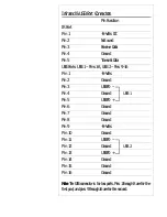


Other Onboard Connectors
Pin Function
Power Input Connector J1
Pin 1
Powergood
Pin 2
+5-Volts DC
Pin 3
+12-Volts DC
Pin 4
–12-Volts DC
Pin 5
Ground
Pin 6
Ground
Pin 7
Ground
Pin 8
Ground
Pin 9
–5-Volts DC
Pin 10
+5-Volts DC
Pin 11
+5-Volts DC
Pin 12
+5-Volts DC
IDE Activity LED Connector J5
Pin 1
+ Positive (cathode) pin
Pin 2
– Negative (anode) pin
Pin 3
– Negative (anode) pin
Pin 4
+ Positive (cathode) pin
CPU Fan Power Connector JP9
Pin 1
Ground
Pin 2
+12-Volts DC for fan power
Pin 3
Ground
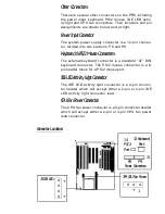
Power Supply Lead Connectors
Some system power supplies have two
leads that connect to the J1 power in-
put connector. If this is the case, you
must connect the power supply leads
so that the black wires are grouped to-
gether in the middle.
!
Summary of Contents for PR5
Page 10: ...System Block Diagram ...


