


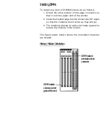


The two Enhanced IDE Controller connectors are for the
two IDE channels Channel 1 and Channel 2. Channel 1
is the Primary channel and is divided in two as the Pri-
mary Master and Primary Slave. Channel 2 is the Sec-
ondary channel and is organized the same way. There
are ribbon cables for each channel. Enhanced IDE allows
a total of four devices, two attached to each IDE channel.
The first device in each channel attaches to the end of
the cable. A second device attaches to the connector in
the middle and the other end of the cable attaches to the
mainboard.
Your start-up (boot) IDE hard disk drive must be con-
nected as the Primary Master (end of the cable). You can
attach a second hard drive in any of the other three avail-
able positions.
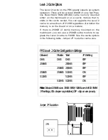
The location of the connectors and their Pin 1 positions
are shown in the Configuration Quick Reference.
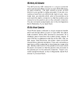
I/O Port Connectors
The PR5 has two serial ports, a parallel port, an infrared
port and a dual-port USB connector onboard. Combina-
tion ribbon cable-to-external port cables are supplied for
each connector except the infrared port. The I/O ports
enable you to connect external devices such as modems
and printers to your system. The serial ports are the
COM1 and COM2 ports and the parallel port is the LPT1
printer port. There are also some other devices which
have a parallel interface and can connect to the LPT port.
An example of this kind of device is a parallel interface
external tape backup drive.
The IR (InfraRed) and USB ports are both a new type of
PC port. The IR port allows wireless two-way commu-
nication between your computer and other devices with
IR capability. The Universal Serial Bus is a new specifica-
tion for connecting external peripheral devices with the
same interface.
The location of the connectors and their Pin 1 positions
and the pin assignments for the Infrared and USB ports
are shown in the Configuration Quick Reference.
Summary of Contents for PR5
Page 10: ...System Block Diagram ...


