


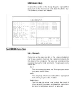


PCI & Onboard I/O Setup
To enter this section of the Setup program, highlight this
menu item in the main menu and press the Enter key.
The following screen will appear.
Award BIOS PCI & Onboard I/O Setup
ROM PCI/ISA BIOS(XXXXXXXX)
PCI & ONBOARD I/O SETUP
AWARD SOFTWARE INC.
ESC : Quit
F 1
: Help
F 5
: Old Values
F 6
: Load BIOS Defaults
F 7
: Load Setup Defaults
¬∅♦
:Select Item
PU/PD/+/- : Modify
(SHIFT)F2 : Color
Onboard FDD Controller
: Enable
Onboard Serial Port 1
: 3F8/IRQ4
Onboard Serial Port 2
: 2F8/IRQ3
-Onboard IR Function
: HPSIR
-IR Duplex Mode
: Half
-IR Tr/Re Polarity
: Hi/Hi
Onboard Parallel Port
: 378/IRQ7
-Parallel Port Mode
: ECP/EPP1.9
-ECP Mode Use DMA
: 3
PCI PnP BIOS Auto-Config
: Disable
PCI IRQ Actived By
: Level
1st Available IRQ
: 9
2nd Available IRQ
: 11
3rd Available IRQ
: 10
4th Available IRQ
: 5
PCI IDE Card 2nd Channel
: Enabled
PCI IDE Card IRQ Map to
: PCI-AUTO
-Primary IDE INT#
: A
-Secondary IDE INT#
: B
PS/2 Mouse Function(IRQ12): Enable
Onboard IDE-1 Controller
: Enable
-Master Drive PIO Mode
: AUTO
-Slave Drive PIO Mode
: AUTO
Onboard IDE-2 Controller
: Enable
-Master Drive PIO Mode
: AUTO
-Slave Drive PIO Mode
: AUTO
Menu Commands
The menu commands for this screen are the same as for
the BIOS Features Setup screen.
PCI PnP BIOS Auto-Config
This function will automatically assign IRQs to PCI ex-
pansion slot INT#s as needed when enabled. If disabled,
IRQs are assigned via the Available IRQ settings that fol-
low after the next item. The default setting is Disabled.
PCI IRQ Actived By
The Level setting is required, don’ t change it.
Available IRQ
These four lines allow setting which IRQs will be assigned
as needed to PCI expansion slot INT#s. The sequence
controls the order in which the IRQs are assigned. The
system looks at the PCI slots in the order Slot 1, 2, 3. The
IRQ options are 3, 4, 5, 7, 9, 10, 11, 12, 14 and 15.
Summary of Contents for PR5
Page 10: ...System Block Diagram ...


