Chapter 2
SA7
3-10
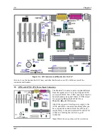
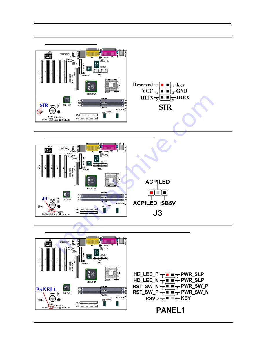
(15). SIR: IR Header (Infrared)
There is a specific orientation for pins 1 through 6,
attach the connector from the IR KIT or IR device to
the IR1 header. This motherboard supports standard
IR transfer rates.
Note:
Watch the pin position and the orientation
(16). J3: 3 Pins Single-Color LED header (5V Standby LED)
By connecting the LED here, the LED will light up
after the power switch is pressed. This LED will
show you the 5V standby power situation.
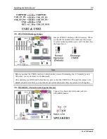
(17). PANEL1: The Headers for Chassis’s Front Panel Indicators and Switches
FPIO1 are for switches and indicators for the
chassis’ front panel. There are several functions that
come from this header. You have to watch the pin
position and the orientation, or the LED may not
light up. The figure below shows you the FPIO1
functions of the pins.


