Installing the Motherboard
User’s Manual
3-7
Caution
If the power supply connectors are not properly attached to the ATX power supply, the power supply
or add-on cards may be damaged.
One end of AC power core connects to ATX power supply, and the other end (AC plug) will plug into
the wall outlet. Be aware that when facing the wall outlet, the round hole is in the middle. The right
side slot is called ground wire slot. It has a longer slot length than the left side slot. The left side slot is
called the live wire slot. You can use an electroscope to detect its polarity or you can use a voltage
meter to measure the voltage of both slot sides. If you insert an electroscope into the live wire slot, the
electroscope will light up. Using a voltage meter, you will find that the live wire slot will register a
higher voltage.
If you reverse the polarity of AC plug, it may affect the life of computer equipment, or cause an
electric shock when you touch the computer chassis. We suggest that you plug the computer AC plug
to a three-hole wall outlet for better safety and to avoid electric shock.
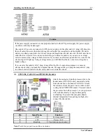
(2). CPUFAN1, CASFAN1 and PWRFAN1 Headers
Attach the connector from the processor fan to the
header named CPUFAN1 and connector from the
front chassis fan to the header CASFAN1. Attach
the connector from the power fan or Add-on card
cooling fan to PWRFAN1 header. You must attach
the processor fan to the processor, or your processor
will work abnormally or may be damaged by
overheating. To prevent the computer chassis
internal temperature from getting too high, also
connect the chassis fan.
Pin Signal
Name
Function
1
GND System
ground
2
+12V Power
+12V
3
Rotation
Fan rotation speed sensor
Note:
Watch the pin position and the orientation
Summary of Contents for SG-71
Page 2: ......
Page 50: ...Chapter 3 SG 71 3 18 ...
Page 84: ...Appendix A SG 71 A 4 ...
Page 88: ...Appendix B SG 71 B 4 ...
Page 92: ...Appendix C SG 71 C 4 ...
Page 110: ...Appendix H SG 71 H 6 ...
Page 114: ...Appendix I SG 71 I 4 ...

