background image

Driver & Utility 


SG-80DC 

4-1 

4. Driver & Utility 

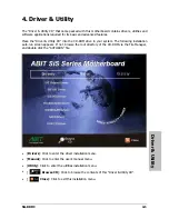
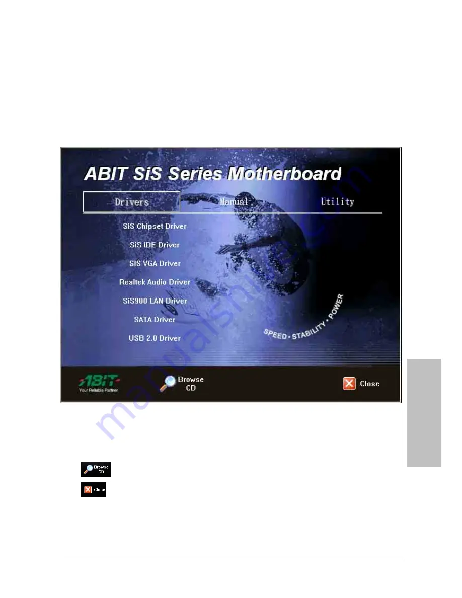
The “Driver & Utility CD” that came packed with this motherboard contains drivers, utilities and 
software applications required for its basic and advanced features. 

Place the “Driver & Utility CD” into the CD-ROM drive in your system. The following installation 
auto-run screen appears. If not, browse the root directory of the CD-ROM via the File Manager, 
and double click the “AUTORUN” file. 


• 

[

Drivers

]: Click to enter the driver installation menu. 

• 

[

Manual

]: Click to enter the user’s manual menu. 

• 

[

Utility

]: Click to enter the utilities installation menu. 

• 


Browse CD

]: Click to browse the contents of this “Driver & Utility CD”. 

• 


Close

]: Click to exit this installation menu. 

Summary of Contents for SG-80DC

Page 1: ...Introduction Hardware Setup BIOS Setup Driver Utility Appendix SG 80DC Motherboard Intel Pentium 4 Socket 775 Installation Instruction ...

Page 2: ...al or consequential damages arising from any defect or error in this manual or product Product names appearing in this manual are for identification purpose only and trademarks and product names or brand names appearing in this document are the property of their respective owners This document contains materials protected under International Copyright Laws All rights reserved No part of this manua...

Page 3: ... 2 5 2 4 1 ATX Power Connectors 2 5 2 4 2 FAN Power Connectors 2 5 2 4 3 Front Panel Switches Indicators Headers 2 6 2 5 Installing Hardware 2 7 2 5 1 CPU Socket 775 2 7 2 5 2 DDR Memory Slots 2 10 2 5 3 Floppy and IDE Disk Drive Connectors 2 11 2 5 4 Serial ATA Connectors 2 12 2 5 5 Accelerated Graphics Port Slot 2 13 2 5 6 PCI Add on Slots 2 13 2 6 Connecting Optional Devices 2 14 2 6 1 Addition...

Page 4: ...3 BIOS Setup 3 1 4 Driver Utility 4 1 5 Appendix 5 1 5 1 Troubleshooting How to Get Technical Support 5 1 5 1 1 Q A 5 1 5 1 2 Technical Support Form 5 3 iv SG 80DC ...

Page 5: ...400 Un buffered Non ECC memory Supports maximum memory capacity up to 2GB Graphics Integrated SIS Mirage Graphics GPU high performance 256 bit 3D engine and 2D Accelerator Serial ATA 2x SATA 1 5Gb s Supports SATA RAID 0 RAID 1 LAN Onboard 10 100M PHY Audio Onboard 5 1 channels Audio CODEC Expansion Slots 1x AGP 8X slot 3x PCI slots Internal I O Connectors 1x Floppy port 1x UDMA 133 100 66 33 conne...

Page 6: ...el Port 1x VGA connector 4x USB 2 0 connectors 1x RJ 45 LAN Connector 1x Audio connector Line out Line in MIC in Miscellaneous ATX form factor 244mm x 244mm Specifications and information contained herein are subject to change without notice 1 2 SG 80DC ...

Page 7: ...Introduction 1 2 Motherboard Layout SG 80DC 1 3 ...

Page 8: ...1 4 SG 80DC ...

Page 9: ... for I O shield located at the rear panel Make sure the I O shield of the chassis matches the I O port configuration of this motherboard You can find an I O shield specifically designed for this motherboard in its package 2 2 Installing Motherboard Most computer chassis have a base with many mounting holes to allow the motherboard to be securely attached and at the same time prevent the system fro...

Page 10: ...e them tightened Face the chassis s rear panel To prevent shorting the PCB circuit please REMOVE the metal studs or spacers if they are already fastened on the chassis base and are without mounting holes on the motherboard to align with 2 3 Checking Jumper Settings For a 2 pin jumper plug the jumper cap on both pins will make it CLOSE SHORT Remove the jumper cap or plug it on either pin reserved f...

Page 11: ...gured to the default values stored in BIOS Pins 2 and 3 shorted default Normal operation Pins 1 and 2 shorted Clear CMOS memory To clear the CMOS memory and load in the default values 1 Power off the system 2 Set pin 1 and pin 2 shorted by the jumper cap Wait for a few seconds Set the jumper cap back to its default settings pin 2 and pin 3 shorted 3 Power on the system 4 For incorrect CPU ratio cl...

Page 12: ...he backup battery 1 Power off the system and disconnect with AC power source 2 Remove the exhausted battery 3 Insert a new CR2032 or equivalent battery Pay attention to its polarity The side is its positive polarity 4 Connect AC power source and power on the system 5 Enter the BIOS setup menu Reconfigure the setup parameters if necessary CAUTION Danger of explosion may arise if the battery is inco...

Page 13: ...in only one orientation find the correct one and push firmly down into these connectors 2 4 2 FAN Power Connectors These connectors each provide power to the cooling fans installed in your system CPU_FAN Power connector for CPU cooling fan SYS_FAN System Fan Power Connector PWR_FAN Auxiliary Fan Power Connector These fan connectors are not jumpers DO NOT place jumper caps on these connectors ...

Page 14: ... to the pin in the figure below stands for positive polarity for the LED connection Please pay attention to connect these headers A wrong orientation will only cause the LED not lighting but a wrong connection of the switches could cause system malfunction Pin Definition Pin Definition 1 HD LED 2 Message LED 3 HD LED 4 Message LED 5 RESET 6 Power Switch 7 RESET 8 Power Switch 9 Reserved 2 6 SG 80D...

Page 15: ...e cap when the CPU is not in use 2 5 1 CPU Socket 775 1 Place the board so as to let the lever hook of the socket is on your left side Use your left thumb and forefinger to hold the lever hook pull it away from the retention tab Rotate the lever to fully open position 2 Use your right thumb on the bottom right side of the load plate and lift it up to fully open position 3 Use your right thumb and ...

Page 16: ...load plate and use your right thumb to peel the cap off The cap plays an important role in protecting contact pins In order to prevent bent pin PUT ON the cap after operation or testing 6 Lower the plate onto the CPU package Engage the load lever while gently pressing down the load plate 7 Secure the lever with the hook under retention tab 2 8 SG 80DC ...

Page 17: ...h the four pin power plug from the heatsink and fan assembly to the CPU FAN connector The installation procedures vary with different types of CPU fan and heatsink assembly The one shown here is served for demo only For detailed information on how to install the one you bought refer to its installation guidelines A higher fan speed will be helpful for better airflow and heat dissipation Neverthele...

Page 18: ...hing its connectors 3 Align the notch key on the module with the rib on the slot 4 Firmly press the module into the slots until the ejector tabs at both sides of the slot automatically snaps into the mounting notch Do not force the DIMM module in with extra force as the DIMM module only fit in one direction 5 To remove the DIMM modules push the two ejector tabs on the slot outward simultaneously a...

Page 19: ...1 on both the FDD port and the floppy connector Each of the IDE port connects up to two IDE drives at Ultra ATA 100 mode by one 40 pin 80 conductor and 3 connector Ultra ATA 66 ribbon cables Connect the single end blue connector at the longer length of ribbon cable to the IDE port of this board the other two ends gray and black connector at the shorter length of the ribbon cable to the connectors ...

Page 20: ... array for RAID 0 or RAID 1 configuration is also provided through these SATA connectors To connect SATA device 1 Attach either end of the signal cable to the SATA connector on motherboard Attach the other end to SATA device 2 Attach the SATA power cable to the SATA device and connect the other end from the power supply 2 12 SG 80DC ...

Page 21: ...ot This slot supports an optional AGP graphics card up to AGP 8X 4X mode This motherboard does not support 3 3V AGP cards Use only 1 5V or 0 8V AGP cards 2 5 6 PCI Add on Slots These slots provide the connection of add on cards that comply with PCI specifications ...

Page 22: ...nal USB 2 0 ports by connecting bracket or cable to the rear I O panel or the front mounted USB ports of your chassis Pin Pin Assignment Pin Pin Assignment 1 VCC 2 VCC 3 Data0 4 Data1 5 Data0 6 Data1 7 Ground 8 Ground 10 NC Make sure the connecting cable bears the same pin assignment 2 6 2 Internal Audio Source Connector This connector connects to the audio output of internal CD ROM drive or add o...

Page 23: ...ct the extension cable attach the jumpers back at pin 5 6 and pin 9 10 default setting Pin Signal Name Function 1 AUD_MIC Front Panel Microphone input signal 2 AUD_GND Ground used by Analog Audio Circuits 3 AUD_MIC_BIAS Microphone Power 4 AUD_VCC Filtered 5V used by Analog Audio Circuits 5 AUD_F_R Right Channel audio signal to Front Panel 6 AUD_RET_R Right Channel Audio signal to Return from Front...

Page 24: ...ort connector COM1 Serial port connector VGA1 Monitor signal connector USB1 USB2 USB 2 0 connectors LAN1 10 100Mbps LAN connector AUDIO Line In Connects to the line out from external audio sources Line Out Connects to the front left and front right channel in the 5 1 channel or regular 2 channel audio system Mic In Connects to the plug from external microphone 2 16 SG 80DC ...

Page 25: ...en the memory count begins and then the following message appears on the screen PRESS DEL TO ENTER SETUP If this message disappears before you respond restart the system by pressing Ctrl Alt Del keys or by pressing the Reset button on computer chassis Only when it failed by these two methods can you restart the system by powering it off and then back on After pressing Del key the main menu screen ...

Page 26: ...3 2 SG 80DC ...

Page 27: ... CD ROM drive in your system The following installation auto run screen appears If not browse the root directory of the CD ROM via the File Manager and double click the AUTORUN file Drivers Click to enter the driver installation menu Manual Click to enter the user s manual menu Utility Click to enter the utilities installation menu Browse CD Click to browse the contents of this Driver Utility CD C...

Page 28: ...4 2 SG 80DC ...

Page 29: ... enter the BIOS setup page to apply the correct settings If the situation remains the same repeat the procedures in Step 1 for three times or try Step 2 Step 2 Switch off the power supply unit or disconnect the power cord Open the chassis cover Locate the CCMOS jumper near the button battery Change the jumper position from default 2 3 to 1 2 for one minute to discharge the CMOS data and then put i...

Page 30: ...Catalyst 5 12V Power supply maker Type in the brand and model name of your power supply unit Power supply wattage Type in the power wattage of your power supply unit Storage devices Type in the brand and specifications of your HDD drive and quantity Specify if it was inserted on IDE Master or Slave or SATA ports including the RAID allocation status Example 1 WD Caviar WD600 60GB on IDE2 master Max...

Page 31: ...rst name Last Name Subject Motherboard BIOS Version CPU Memory brand Memory size Memory configuration Graphics card Graphics driver version Power supply maker Power supply wattage Storage devices Optical devices Other devices Operating system Problem description ...

Page 32: ...Rev 1 00 ABIT Computer Corporation http www abit com tw ...

Reviews: