background image

Page 4

Rev Oct 2013

3. Connecting the player unit

3.1.

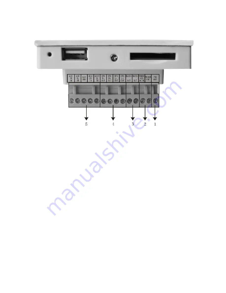
Antenna wire

(1)

[FM ANT]

Preferably run a solid wire with diameter <1mm with a length of minimum 1,5m, in a vertical plane,
as close to the surface of the wall as possible.

3.2.

Low voltage power jumper

(2)

[POWER +12 VDC IN] and [POWER GND]

Run a 2x 0,75mm² multi-stranded wire between power unit back box and media player back box.
Red/black speaker wire is convenient, the red wire being the “+” terminal, the black one being the “-“
or ground terminal.

3.3. Line out to amplified subwoofer

(3)

[BASS+ OUT] and [BASS- OUT

Run a good quality shielded audio cable between the media player unit and an active subwoofer unit
(not supplied) to enhance the bass response.

3.4.

Loudspeaker cables (right and left channel)

(4)

[SPK R- OUT]  *  [SPK R+ OUT]   /  [SPK L- OUT] *  [SPK L+ OUT]

Loudspeaker cables should be 2x0,75mm² multi-strand wires with a red/black color scheme.
Connect the black leads to the “-“ terminals and the red leads to the “+”  terminals.
Do not tie together the two black or the two red leads.

Summary of Contents for ABI-MU3001SBT

Page 1: ...Page 1 Rev Oct 2013 ABI MU3001SBT User s Manual FM Radio Media player Stereo amplifier kit...

Page 2: ...4 4 3 5 Line input AUX1 and AUX2 audio cables 5 5 3 6 Mediaplayer Wiring diagram 5 4 Connecting the power supply unit 6 4 1 Low voltage power jumper cfr 3 2 6 4 2 Mains power cord 6 5 Power up and te...

Page 3: ...any parts yourself The power supply is directly fed from the mains Please never touch the mains terminals or open the device when it is under power 2 Preparing the installation 2 1 Mounting the back...

Page 4: ...s convenient the red wire being the terminal the black one being the or ground terminal 3 3 Line out to amplified subwoofer 3 BASS OUT and BASS OUT Run a good quality shielded audio cable between the...

Page 5: ...dio cables 5 AUX 1R IN AUX 1L IN GND AUX 2R IN AUX 2L IN Run one or two good quality shielded stereo audio cable between the mediaplayer unit and the wall outlets that will be used to connect AUX1 and...

Page 6: ...mm multi stranded wire between the orange terminals power unit and media player Red black speaker wire is convenient the red wire being the terminal the black one being the or ground terminal 4 2 Main...

Page 7: ...is on Touch this button to RETURN to the previous menu page 6 2 Button CONFIRM PLAY PAUSE Touch this button to drill down into a submenu Touch this button to PAUSE playing when the unit is playing Tou...

Page 8: ...tracks when playing music Touch these buttons for 3 seconds to do fast forward or fast back when playing music 7 BOTTOM Connectors 7 1 SD card slot 8 Plug in an SD card with music or pictures The unit...

Page 9: ...FF Push the switch at the bottom of the power supply unit to the right The blue light under the glass front will glow The media player unit now boots up and displays the music menu The media player ca...

Page 10: ...to confirm you Bluetooth selection Find available Bluetooth devices with your smartphone Connect to F 3086 11 Play PICTURES Select the picture menu and then touch the OK button to enter the submenu I...

Page 11: ...nt panel to navigate to the AUX menu then OK to enter Press the AUX button on the remote control to switch between AUX1 AUX2 and AUX or use the buttons on the front panel 14 TIMER setup Press the ALAR...

Page 12: ...to avoid repetitive upgrades every time you insert the SD card WARNING should a power outage occur when upgrading the program will be lost and the unit will not start up again Don t upgrade if you do...

Reviews: