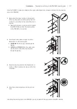
| Installation –
Preparation for installing the PVEMH10 mounting plate
14
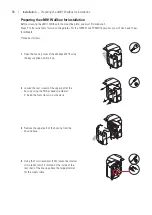
Preparation for installing the PVEMH10 mounting plate
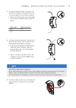
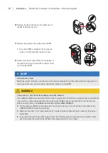
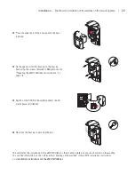
If you are installing the PVEMH10 mounting plate, you will need to install the supplied coupling relay in the eMH1
Wallbox and then establish a connection to the inverter of the PV system (see
Steps 7
to
9
cal installation of the wallbox on the mounting plate” from page 21 onwards).
When the PVEMH10 selector switch is set to
ECO
, the inverter enables the charging process based on the power
threshold set for the system in the
ABL Configuration Software
.
NOTE
Information on the inverter and wiring
Please read the operating instructions for your inverter before installation. All the requirements for the control
cables as well as the permissible peak voltages for the control cables will be specified there.
You’ll also be able to find out how to set the threshold value for enabling the charging process. The threshold
value is the power at which the inverter enables charging in
ECO
charging mode.
When selecting the threshold value, you should always take into account the size of the PV system, the
average consumption for your own use and the charging power of the eMH1 Wallbox set in the
ABL Config-
uration Software
.
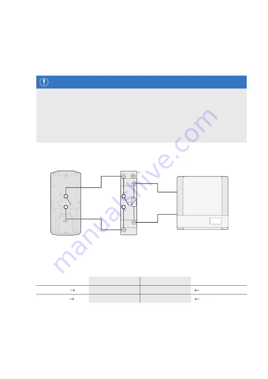
Operation with an inverter with digital output
Can be used for inverters with a control output with switching voltages from 8 to 230 V AC/DC.
+A1
1(L)
-A2
2
N
PVEMH10
Relay
Inverter PV system
You must always provide an appropriate cable connection to the inverter at the installation location, which is then
connected to the
+A1
and
-A2
contacts of the relay. The allocation is shown in the following table.
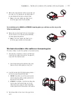
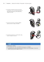
The connection itself is described in
Step 7
in section “Mechanical installation of the wallbox on the mounting plate”
PVEMH10
Relay terminal
Relay contact
Inverter
Black wire
1 (L)
+A1
Relay control terminal A
Blue wire
2
-A2
Relay control terminal B


