Installation –
Screwing to the wall |
15
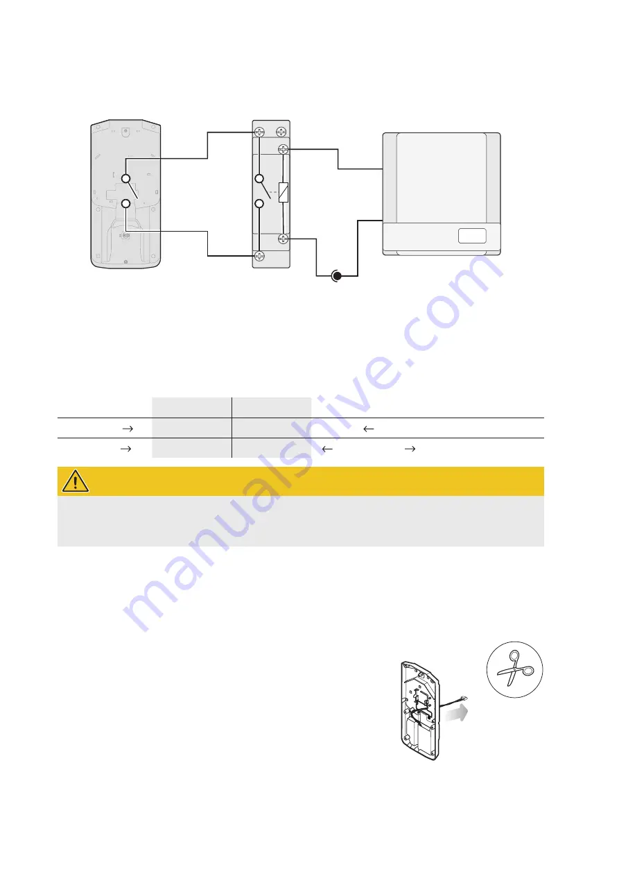
Operation with an inverter with floating output
Can be used for inverters with a control output with switching voltages from 8 to 230 V AC/DC.
+A1
1(L)
-A2
2
N
− 8 ~ 230 V +
PVEMH10
Relay
Power supply unit
Inverter PV system
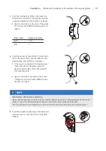
For an inverter with a floating output, you will need to provide a power supply via the supplied top-hat rail power sup-
ply unit. Install the power supply unit in a suitable switch cabinet or similar and then lay the cable at the installation
location. The allocation is shown in the following table.
The connection itself is described in
Step 8
in section “Mechanical installation of the wallbox on the mounting plate”
on page 21.
PVEMH10
Relay terminal
Relay contact
Power supply unit 12 V
Inverter
Black wire
1 (L)
+A1
Relay control terminal A
Blue wire
2
-A2
Minus/Plus pole
Relay control terminal B
WARNING!
Maximum cable length between power supply unit, inverter and relay
Please note that the length of the cables between the power supply unit and the inverter or relay must not ex-
ceed 30 metres.
Screwing to the wall
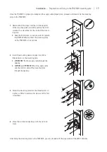
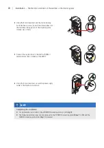
Once the installation location has been prepared, you can screw the mounting plate to the wall.
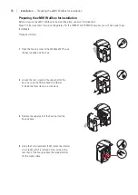
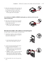
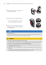
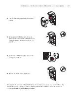
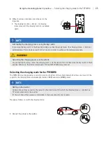
Proceed as follows to prepare the 1W0001 and PVEMH10 mounting plates:
1
Loosen the control cable which is fixed to the back
of the 1W0001/PVEMH10 with a cable tie.
2
Run it through the opening to the front of the
mounting plate.


