Installation –
Mechanical installation of the wallbox on the mounting plate |
19
5
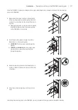
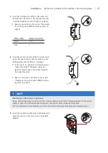
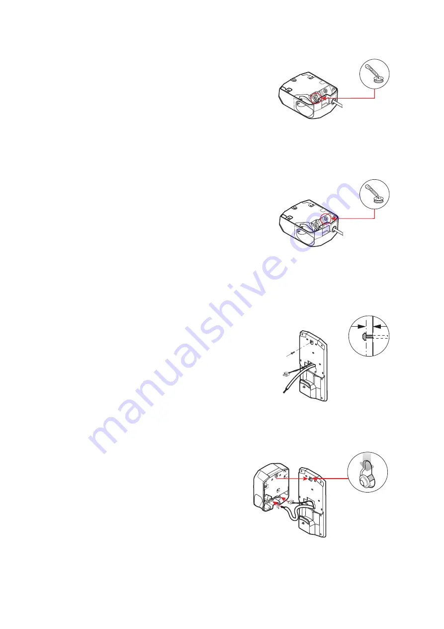
Remove the large grommet for the supply cable, use
the cutter to cut an opening for the supply cable in
the membrane and then replace the grommet.
y
Step 2
in the next chapter describes how to
insert the supply cable into the wallbox.
For installation on the 1W0001 and PVEMH10 mounting plates, you will also need to carry out the
following working step:
6
Remove the small grommet for the control cable(s),
use the cutter to cut an opening in the membrane
and then replace the grommet.
y
Step 2
in the next chapter describes how to
insert the supply cable(s) into the wallbox.
Mechanical installation of the wallbox on the mounting plate
Proceed as follows to attach the wallbox to the mounting plate:
1
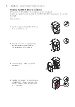
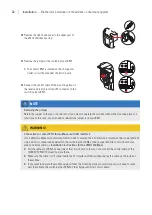
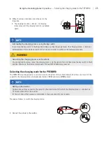
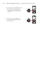
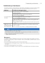
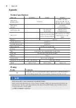
Using the Torx screwdriver, screw a 5×20 flat-head
screw from the scope of delivery into the upper fix-
ing point of the mounting plate.
4 mm
y
The distance between the bottom of the screw
head and the mounting plate must be 4 mm.
2
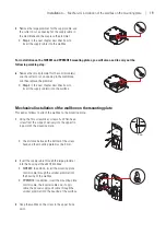
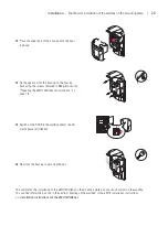
Insert the supply cable through the large grommet
into the housing of the eMH1 Wallbox.
y
1W0001:
In addition, insert the mounting plate
control cable through the smaller grommet into
the housing of the wallbox.
y
PVEMH10:
In addition, insert the mounting plate
control cable, the inverter cable and, if appli-
cable, the power supply unit cable through the
smaller grommet into the housing of the wallbox.
3
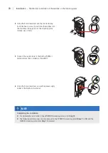
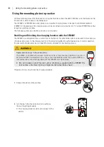
Hang the wallbox on the screw in the upper fixing
point.


