Installation –
Mechanical installation of the wallbox on the mounting plate |
21
7
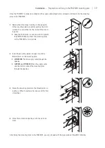
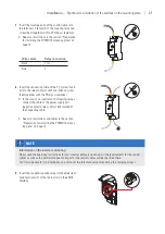
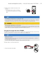
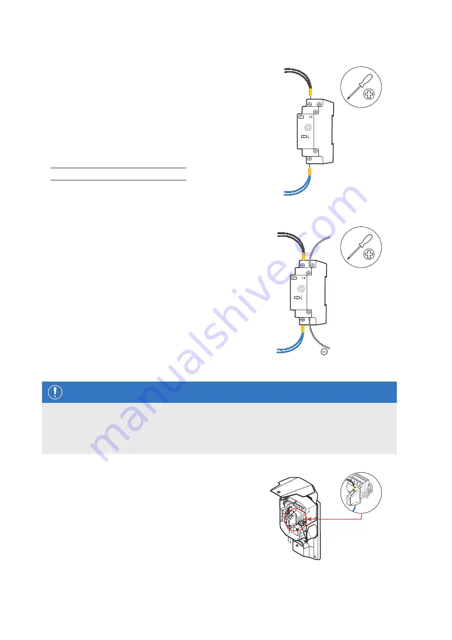
Insert the two free ends of the control cable into
the terminals
1 (L)
and
2
of the coupling relay and
screw them together with the Phillips screwdriver.
y
See also illustrations in the section “Preparation
for installing the PVEMH10 mounting plate” on
μ
+A1
-A2
+A1
1(L)
-A2
2
N
16A/250V~
Wire colour
Relay connection
black
1 (L)
blue
2
8
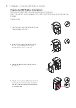
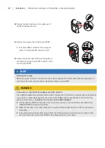
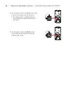
Insert the connecting cable of the PV system invert-
er into the relay contacts
+A1
and
-A2
and screw
them together with the Phillips screwdriver.
y
In the case of an inverter with a floating output,
connect the cable of the power supply unit
(negative pole) to relay contact
-A2
instead of
the connecting cable.
y
See also illustrations and tables in the section
“Preparation for installing the PVEMH10 mount-
μ
+A1
-A2
1(L)
-A2
2
N
16A/250V~
+A1
( )
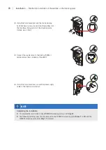
NOTE
Information on the inverter and wiring
Please read the operating instructions for your inverter before installation. All the requirements for the control
cables as well as the permissible peak voltages for the control cables will be specified there.
You’ll also be able to find information on how to set the threshold value for enabling the charging process.
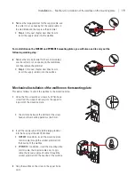
9
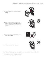
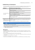
Insert the supplied coupling relay into the free right-
hand terminal slot of the top-hat rail in the eMH1
Wallbox.


