20
4.5. No LEDs and No Output
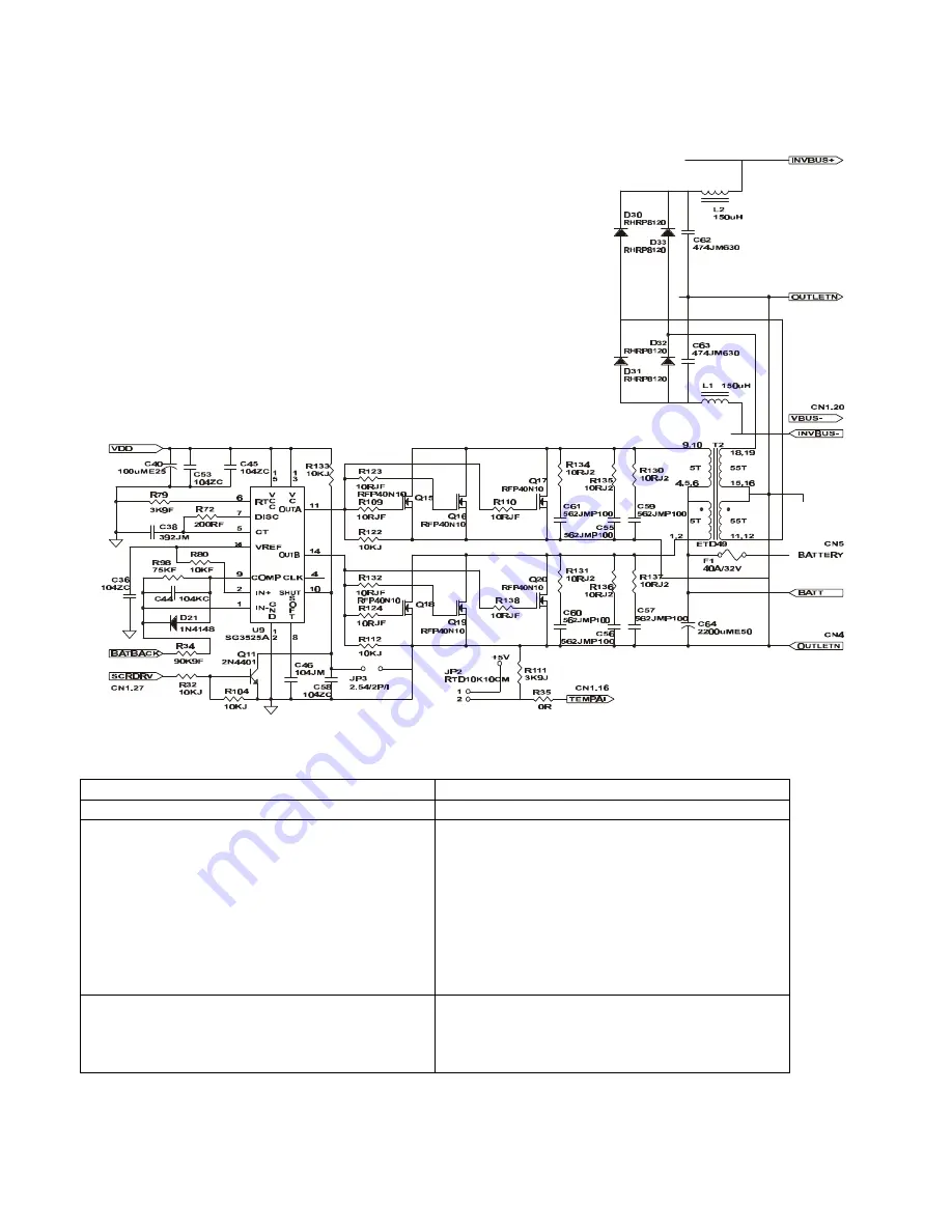
FIG. 4.5
Check Items
Trouble-shooting
Power Devices defective, AC or DC fuse is burn
Please see table 4.3 and 4.4 .
The working voltage of the control board is out
of order.
1. Please check the circuit shown in fig.4-2.
2. Cut off the Utility. Remove the control board.
Supply a 36Vdc to CN5 and CN4 by a DC
Power supply, connect CN2 to the main switch.
Push on the main switch and to see if DC POWER,
i.e. VDD(17.5V), VCC(12V) and +/-5V is normal.
3. Check if Q1, Q6, Q7, Q25, D11, D12 and U4
Is normal.
4. Check if any abnormal output signal of the U9.
CPU is down.
If the DC POWER is normal, the CPU could be
Down. Remove the battery harness from the
UPS and re-connect it back to its position.
Summary of Contents for 3 MS series
Page 7: ...7 1 2 3 4 5 6 7 8 9 Pin 6 RS232 Rx Pin 9 RS232 Tx Pin 7 Ground...
Page 24: ...24 5 2 Fault LED Lights up and No Output FIG 5 2...
Page 32: ...32 6 2 Fault LED Lights up and No Output FIG 6 2...
Page 39: ...39 Appendix a 1 Wiring Diagram a 1 1 For MS 1K...
Page 41: ...41 a 1 3 For MS3K...
Page 42: ...42 a 2 Placements a 2 1 For MS1K 220V...
Page 43: ...43 a 2 2 For MS2K 220V a 2 3 For MS3K...
Page 44: ...44 a 2 3 For MS3K 220V...
Page 45: ...45 a 2 4 For MS1K 120V...
Page 46: ...46 a 2 5 For MS2K 120V...


