24
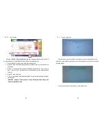
Default screen is as shown above. The individual blocks are described below:
Click Block A to enter the Main. The menu items are as shown in
section5.1.2.
Block B is the status display area. The display is divided into the upper and
lower row.
1. Upper Status: No UPS output, INV Output...
…
etc.
2. Lower Status: Rectifier input normal and Bypass input normal.
Click on Block C Help shows information about each block on the main
screen and a tree diagram of the menu options.
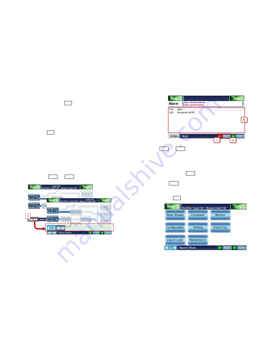
Block D shows the UPS ID needed to observe and the IDs list via clicking
the block D. Procedure of modifying the UPS ID shows as following figure.
Attention: “Master” has to exist in the ID list as following and then
selecting SYS will work on.
Block E shows “Master” or “Slave” with the selected ID of UPS.
Attention: Block E will not appear with unitary mode.
Block F shows the current mode and command progress.
Block G shows the Alarm and Status alerts.
25
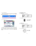
The Alarm and Status alerts are shown above and described as below:
Block Ι shows the warning lights. Green light means there are no alarms.
Blinking red light means that alarm is currently active.
Block
Ⅱ
has the function buttons. Click to display the current status in
Block
Ⅲ
.
In Block
Ⅲ
, when Alarm is chosen for display then blue text shows past
alarms; red means the alarm is currently active. When the selected display
area is Status, this display area will list the current system status.
5.1.2.
Main Menu
Selecting the Main brings up the UPS settings as pictured below.


