42
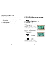
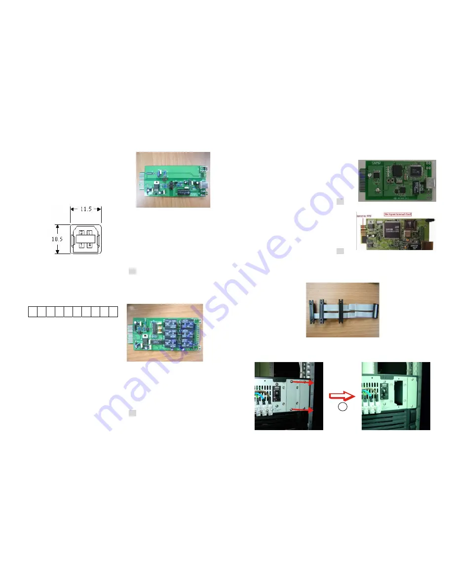
6.4. USE(USB)
card
6.4.1. CN1 for USB and CN3 for EPO.
6.4.2. For communication protocol, please
see the definition below:
Comply with USB version 1.0,1.5Mbps
Comply with USB HID Version 1.0.
The Pin Assignments of the USE card:
6.4.3. Installation Position: slot1 or slot 2.
6.4.4. Adapted flat cable: cable A or cable B
6.4.5. For installation, please refer to Chapter 6.7
6.5.
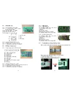
DCE(Dry Contact) card
6.5.1. The pin assignments of 10-Pin Terminal:
1 2 3 4 5 6 7 8 9 10
Pin 1: UPS on Bypass mode.
Pin 2: Utility Normal
Pin 3: Inverter On
Pin 4: Battery Low
Pin 5: Battery Bad or Abnormal
Pin 6: UPS Alarm
Pin 7: Common
Pin 8: Shutdown UPS po ) signal
Pin 9: EPO+
Pin 10: Ground
6.5.2. Installation Position: slot 1 or slot 2
6.5.3. To enable the shutdown function, please short Pin 8 & 10.
6.5.4. Adapted flat cable: cable A or cable B
6.5.5. For installation, please refer to Chapter 6.7
1
Æ
VCC (+5V)
2
Æ
D
-
3
Æ
D
+
4
Æ
Ground
43
1
6.6. SNMP
Cards
6.6.1. SNMP/WEB
card
For installation, please refer to the user’s
manual attached with the card. .
Installation
Position: slot1 or slot 2.
Adapted flat cable: cable A or cable B
For installation, please refer to Chapter 6.7
6.6.2. Net Agent II Internal Card
For installation, please refer to the user’s
manual attached with the card.
Installation
Position: slot 2.
Adapted flat cable: cable C.
For installation, please refer to Chapter 6.7
6.7.
The Installation of those Interface Cards
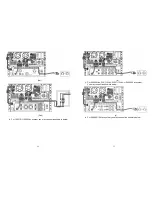
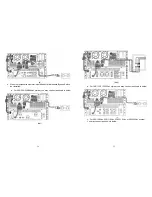
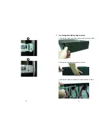
Make sure that the flat cable installed is the same as the one indicated below.
Please proceed the hardware installation as indicated below.
1. Remove the cover of Slot 1.
2. Slide in the selected interface card onto the Slot.
3. Fasten properly the selected interface card.
A
B
C
Summary of Contents for MSII-RT
Page 26: ...50 51 192321142000000 ...

