background image


REGULATORY STATEMENTS 

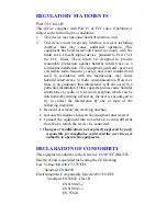
Part15, Class B 

This device complies with Part 15 of FCC rules. Operation is 
subject to the following two conditions: 
1. 

This device may not cause harmful interface, and 

2. 

This device must accept any interface received, including 
interface that may cause undesired operation. This 
equipment has been tested and found to comply with the 
limits for a Class B digital device, pursuant to Part 15 of 
the FCC Rules. These limits are designed to provide 
reasonable protection against harmful interference in a 
residential installation. This equipment generates, uses and 
can radiate radio frequency energy, and if not installed and 
used in accordance with the instructions, may cause 
harmful interference to radio communications. However, 
there is no guarantee that interference will not occur in a 
particular installation. If this equipment does cause harmful 
interference to radio or television reception, which can be 
determined by turning off and on, the user is encouraged to 
try to correct the interference by one or more of the 
following measures: 

• 

Reorient or relocate the receiving antenna. 

• 

Increase the distance between the equipment and receiver. 

• 

Connect the equipment into an outlet on a circuit different 
from that to which the receiver is connected. 

*


Changes or modifications not expressly approved by party 

responsible for compliance could void the user the user 
authority to operate the equipment.


DECLARATION OF CONFORMITY 

This equipment conforms to the Directive 1999/5/EC (R&TTE 
Directive) and is qualified for bearing the CE Marking. 
Low Voltage Directive 72/23/EEC 

Standard: EN60950 

Electromagnetic Compatibility Directive89/336/EEC 

Standard: EN55022: Class B 

EN61000-3-2 
EN61000-3-3 
EN 55024 

Summary of Contents for UAM800

Page 1: ...M73 APO02 560 U US SB B A AD DS SL L M Mo od de em m Q Qu ui ic ck k I In ns st ta al ll la at ti io on n G Gu ui id de e...

Page 2: ...no guarantee that interference will not occur in a particular installation If this equipment does cause harmful interference to radio or television reception which can be determined by turning off and...

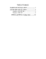
Page 3: ...Table of Contents HARDWARE INSTALLATION 1 SOFTWARE INSTALLATION 2 Windows 98 98SE ME 2 Windows 2000 XP 4 PPPOE and PPPOA Configuration 10...

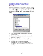
Page 4: ...ger tab check if the Universal Serial Bus controller device is found 1 You can connect this modem without powering down your PC 2 Connect the USB connector on the modem to the USB port of your PC 3 Co...

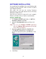
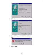
Page 5: ...r computer Windows will detect the new hardware automatically W Wi in nd do ow ws s 9 98 8 9 98 8S SE E M ME E 1 For Windows 98 98SE applications in Add New Hardware Wizard click Next 2 Select the Rec...

Page 6: ...5 Click Next 6 Insert the Windows 98 98SE CD and then click OK 7 Click Finish 3...

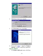
Page 7: ...our computer 9 At the Welcome screen click Next 10 Please refer to step 7 step 13 in Windows 2000 XP section to continue the installation W Wi in nd do ow ws s 2 20 00 00 0 X XP P 1 For Windows 2000 a...

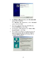
Page 8: ...then click Next 3 Insert the supplied CD into the CD ROM drive Select CD ROM then click Next 4 For Windows 2000 applications in Driver Files Search Results click Next 5 The window may display a warnin...

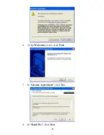
Page 9: ...6 At the Welcome screen click Next 7 In License Agreement click Yes 8 In Read Me click Next 6...

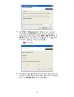
Page 10: ...elect the appropriate driver type from RFC1483 PPPoA or PPPoE You may also see an option to change the VPI VCI settings Then click Next RFC1483 10 Select the appropriate framing setting given by your...

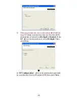
Page 11: ...llow your Internet Service Provider ISP instructions to select from Bridged or Routed If the ISP did not mention about it select Bridged Then click Next In IP Configuration refer to the information pr...

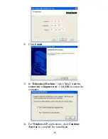
Page 12: ...2 Click Finish 13 In Rebooting Machine select Yes I want to restart my computer now Click OK to restart the computer 14 For Windows XP applications click Continue Anyway to complete the installation 9...

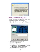
Page 13: ...elow steps to configure the connection 1 Click either the desktop icon or the Dial Up Networking icon to open the Connect To window 2 Provide the following information 1 Supply the User Name 2 Supply...

Reviews: