17. Power down operation
A96G140/A96G148/A96A148 User’s manual
218
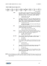
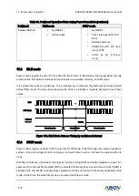
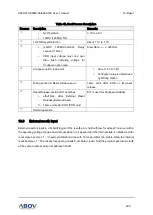
Table 39. Peripheral Operation Status during Power Down Mode (continued)
Peripheral
IDLE mode
STOP mode
Release Method
By RESET
All Interrupts
By RESET
Timer Interrupt (EC0, EC1,
EC3)
External Interrupt
USART2 by RX, WT (sub
clock), WDT
USI0/1
by
RX, I2C(Slave
mode)
17.2
IDLE mode
P
ower control register is set to ‘01h’ to enter
into IDLE mode. In IDLE mode, internal oscillation circuits
remain active. Oscillation continues and peripherals are operated normally, but CPU stops.
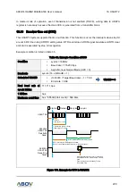
It is released by reset or an interrupt. To be released by an interrupt, the interrupt should be enabled
before IDLE mode. If using a reset, because the device is initialized, registers become to have reset
values.
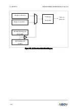
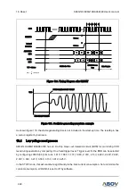
Figure 112. IDLE Mode Release Timing by an External Interrupt
17.3
STOP mode
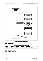
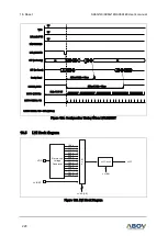
Power control register is set to ‘03H’ to enter into STOP mode. In STOP mode, the selected oscillator,
system clock and peripheral clock is stopped, but watch timer can be continued to operate with sub
clock.
With the clock frozen, all functions are stopped, but the on-chip RAM and control registers are held. For
example, If the internal RC oscillator (fIRC) is selected for the system clock and the sub clock (fSUB) is
oscillated, the internal RC oscillator stops oscillation and the sub clock is continuously oscillated in stop
mode. At that time, the watch timer can be operated with the sub clock.
External
Interrupt
OSC
Normal Operation
Release
CPU Clock
Stand-by Mode
Normal Operation


