A96G140/A96G148/A96A148 User’s manual
2. Pinouts and pin description
25
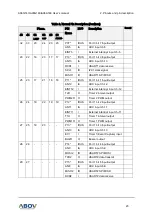
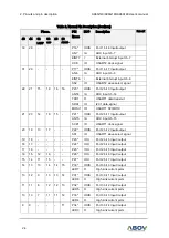
Table 2. Normal Pin Description (Continue)
Pin no.
PIN
Name
I/O
Description
Remark
48 44
32
LQFP
32
SOP
28 28
A96A148
8
8
-
-
-
10
P35*
IOUS
Port 3 bit 5 Input /output
LED2
O
High sink current ports
7
7
-
-
-
9
P36*
IOUS
Port 3 bit 6 Input/output
LED1
O
High sink current ports
6
6
-
-
-
8
P37*
IOUS
Port 3 bit 7 Input/output
LED0
O
High sink current ports
2
2
4
8
8
-
P40*
IOUS
Port 4 bit 0 Input/output
RXD0
I
USART0 data receive
SCL0
IO
I2C0 clock signal
MISO0 IO
USART0 SPI MISO
3
3
5
9
9
-
P41*
IOUS
Port 4 bit 1 Input/output
TXD0
O
USART0 data transmit
SDA0
IO
I2C data signal
MOSI0 IO
USART0 SPI MOSI
4
4
-
10
10 -
P42*
IOUS
Port 4 bit 2 Input/output
SCK0
IO
USART0 clock signal
5
5
-
-
-
-
P43*
IOUS
Port 4 bit 3 Input/output
SS0
IO
USART0 slave select signal
12 -
-
-
-
-
P44*
IOUC
Port 4 bit 4 Input/output
24 -
-
-
-
-
P45*
IOUC
Port 4 bit 5 Input/output
36 -
-
-
-
-
P46*
IOUC
Port 4 bit 6 Input/output
48 -
-
-
-
P47*
IOUC
Port 4 bit 7 Input/output
43 40
30
2
2
2
P50*
IOUS
Port 5 bit 0 Input/output
XOUT O
Main Oscillator Output
44 41
31
3
3
3
P51*
IOUS
Port 5 bit 1 Input/output
XIN
I
Main Oscillator Input
45 42
32
4
4
4
P52*
IOUS
Port 5 bit 2 Input/output
EINT8 I
External interrupt input ch-8
EC0
I
Timer 0(Event Capture) input

