MC80F0304/08/16
November 4, 2011 Ver 2.12
123
5) Select target MCU - It makes condition to make Vpp to
turn on when Vdd is turned on.
6) Power on a target system. : At this point, ISP mode is en-
tered because the Vdd and Vpp are turned on simulta-
neously.
V
DD
RESET
X
IN
X
OUT
V
SS
R05 / TxD
R04 / RxD
R05 / ACLK
R10
ISP Configuration
MCU TxD
MCU RxD
High(1)
V
DD
(+5V)
+9V
2
3
4
5
6
7
8
27
26
25
24
23
22
21
1
28
9
10
11
12
13
14
20
19
18
17
16
15
2MHz~12MHz
ACLK_CLK
ALE
X-TAL
RESET/V
PP
RST/VPP
Tx Data
1
Rx Data
1
ACLK
4
V
DD
(+5V)
ISP Bo
ar
d
V
SS
User target reset circuitry
ISP_V
PP
RST/V
PP
47K
Ω
3
(optional)
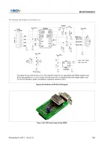
1. If other signals affect UART communiction in ISP mode, disconnect these pins by using a jumper or a switch.
2. The ALEB can be shared with other function. Toggle the port between ISP and user mode.
3. The pull down resister is optional. If user set to ISP Mode without connection ISP board, the Vpp/Reset Port is in floating state.
The pull down resistor is for blocking this undefined state.
4. Refer to the section 26.5 explaining the auto bua drate and ACK mode.
Do not power on a application B/D in ISP mode without connecting a ISP board.


