MC80F0304/08/16
24
November 4, 2011 Ver 2.12
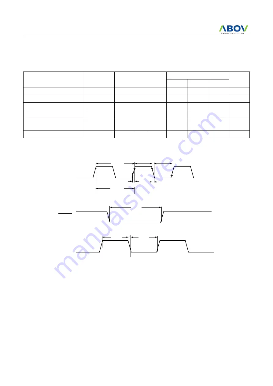
7.5 AC Characteristics
(T
A
=-40~+85
°
C, V
DD
=5V
±
10%, V
SS
=0V)
Figure 7-1 Timing Chart
7.6 Typical Characteristics (MC80F0304/08/16)
These graphs and tables provided in this section are for design
guidance only and are not tested or guaranteed.
In some graphs or tables the data presented are out-
side specified operating range (e.g. outside specified
V
DD
range). This is for information only and devices
are guaranteed to operate properly only within the
specified range.
The data presented in this section is a statistical summary of data
collected on units from different lots over a period of time. “Typ-
ical” represents the mean of the distribution while “max” or
“min” represents (mean + 3
σ
) and (mean
−
3
σ
) respectively
where
σ
is standard deviation
Parameter
Symbol
Pins
Specifications
Unit
Min.
Typ.
Max.
Operating Frequency
f
CP
X
IN
1
-
8
MHz
External Clock Pulse Width
t
CPW
X
IN
50
-
-
nS
External Clock Transition Time
t
RCP,
t
FCP
X
IN
-
-
20
nS
Oscillation Stabilizing Time
t
ST
X
IN
, X
OUT
-
-
20
mS
External Input Pulse Width
t
EPW
INT0, INT1, INT2, INT3
EC0, EC1
2
-
-
t
SYS
RESET Input Width
t
RST
RESET
8
-
-
t
SYS
t
RCP
t
FCP
X
IN
INT0, INT1
INT2,
0.5V
V
DD
-0.5V
0.2V
DD
RESET
0.2V
DD
0.8V
DD
EC0,
t
RST
t
EPW
t
EPW
1/f
CP
t
CPW
t
CPW
t
SYS
INT3
EC1


