MC95FG0128A
78
Aug 02, 2018 Ver.2.9
11.2 BIT
11.2.1 Overview
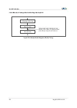
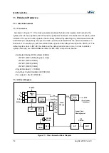
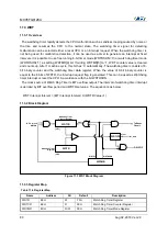
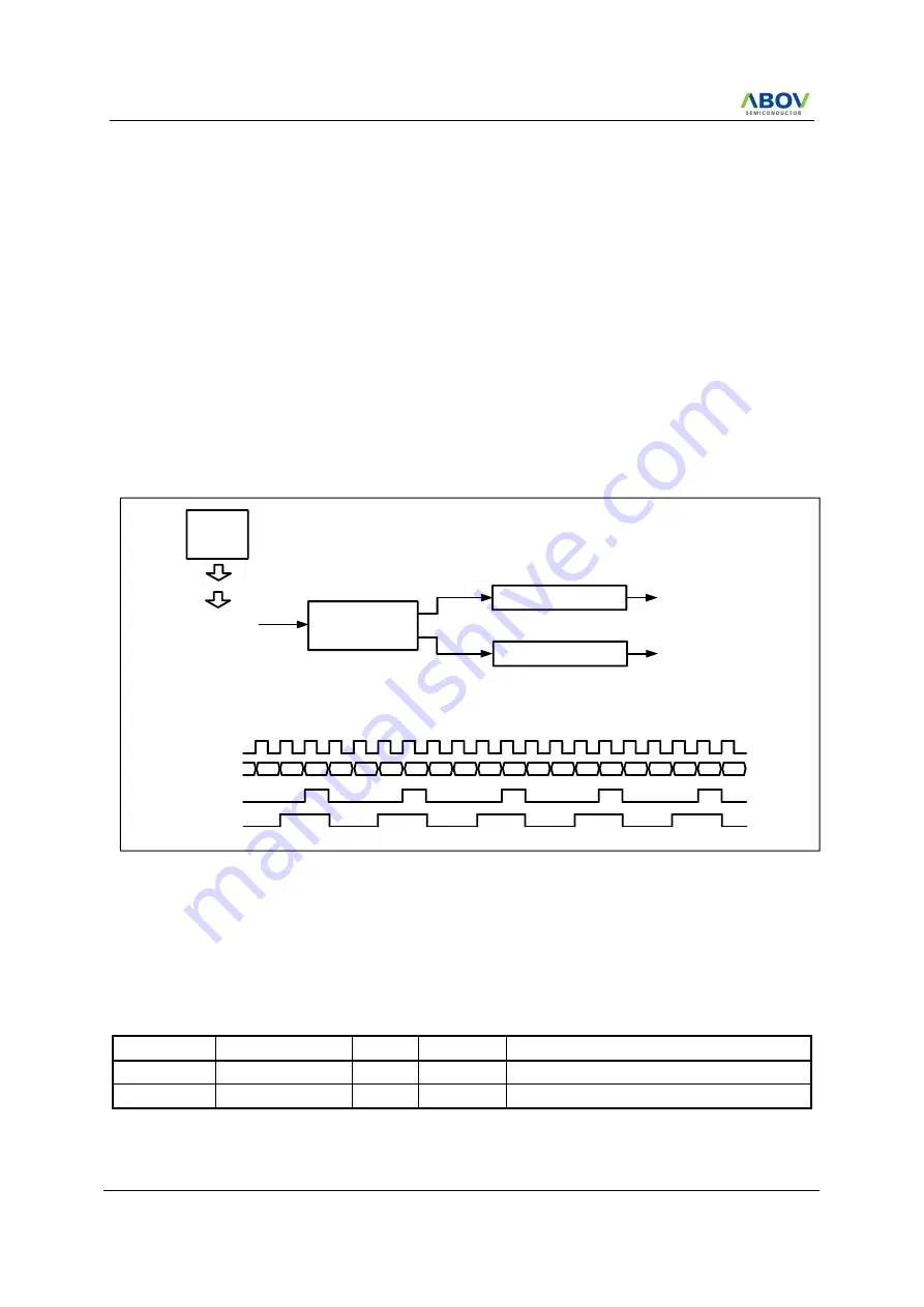
The MC95FG0128A has one 8-bit Basic Interval Timer that is free-
run and can’t stop. Block diagram
is shown in Figure 11.2. In addition, the Basic Interval Timer generates the time base for watchdog
timer counting. It also provides a Basic interval timer interrupt (BITF).
The MC95FG0128A has these Basic Interval Timer (BIT) features:
- During Power On, BIT gives a stable clock generation time
- On exiting Stop mode, BIT gives a stable clock generation time
- As clock function, time interrupt occurrence
11.2.2 Block Diagram
RING-OSC
(1MHz)
BITR (8-bit COUNT)
BIT_CLK
÷ 8
BIT Interrupt Generator
BIT Out Generator
BIT Interrupt Flag
BIT_OUT (WDT clock source)
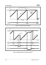
BIT_CLK
0
1
2
3
4
5
6
7
8
9
10
11
12
13
14
15
16
17
18
19
20
BITR
BIT_Int_Flag
BIT_Out
÷ 32
※
1MHz ÷ 8 ÷ 32
≒
3.91KHz
※
BCK[2:0] = 001b
Figure 11.2 BIT Block Diagram
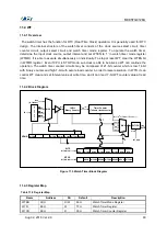
11.2.3 Register Map
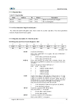
Table 11-3 Register Map
Name
Address
Dir
Default
Description
BCCR
8BH
R/W
05H
BIT Clock Control Register
BITR
8CH
R
00H
Basic Interval Timer Register
Summary of Contents for MC95FG0128A
Page 26: ...MC95FG0128A 26 Aug 02 2018 Ver 2 9 4 Package Diagram Figure 4 1 100 pin LQFP package...
Page 27: ...MC95FG0128A Aug 02 2018 Ver 2 9 27 Figure 4 2 80 pin LQFP package...
Page 28: ...MC95FG0128A 28 Aug 02 2018 Ver 2 9 Figure 4 3 80 pin MQFP package...
Page 29: ...MC95FG0128A Aug 02 2018 Ver 2 9 29 Figure 4 4 64 pin LQFP package...
Page 30: ...MC95FG0128A 30 Aug 02 2018 Ver 2 9 Figure 4 5 64 pin LQFP14 package...

