MC95FG0128A
160
Aug 02, 2018 Ver.2.9
12.3 IDLE mode
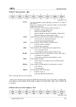
The power control register is set to ‘01h’ to enter the IDLE Mode. In this mode, the internal oscillation
circuits remain active. Oscillation continues and peripherals are operated normally but CPU stops. It is
released by reset or interrupt. To be released by interrupt, interrupt should be enabled before IDLE
mode. If using reset, because the device becomes initialized state, the registers have reset value.
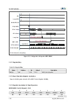
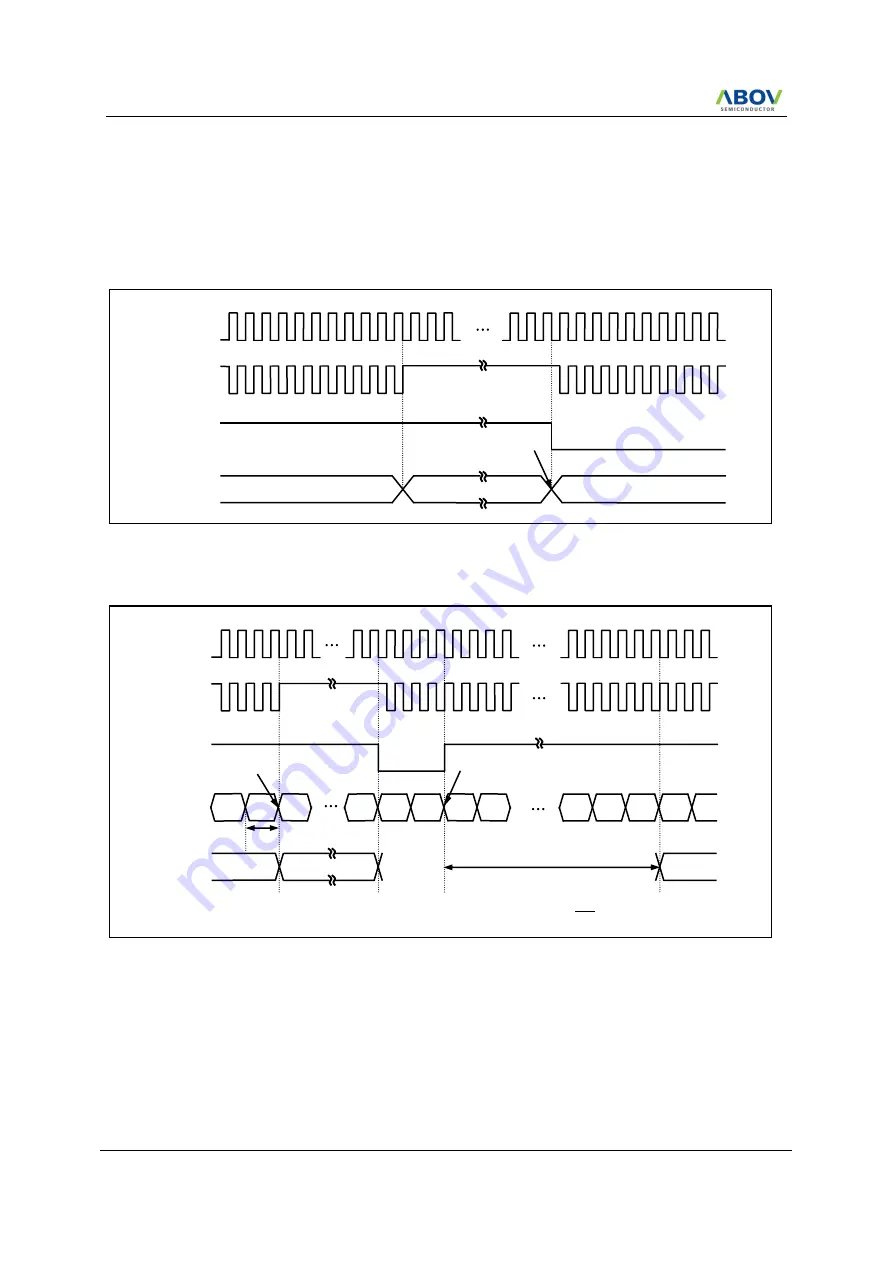
Figure 12.1 IDLE Mode Release Timing by External Interrupt
Figure 12.2 IDLE Mode Release Timing by /RESET
(Ex) MOV PCON, #0000_0001b ; setting of IDLE mode : set the bit of STOP and IDLE Control register
(PCON)
12.4 STOP mode
The power control register is set to ‘03h’ to enter the STOP Mode. In the stop mode, the main
oscillator, system clock and peripheral clock is stopped, but watch timer continue to operate. With the
clock frozen, all functions are stooped, but the on-chip RAM and control registers are held.
External
Interrupt
OSC
Normal Operation
Release
CPU Clock
Stand-by Mode
Normal Operation
OSC
CPU Clock
RESETB
Normal Operation
BIT Counter
SLEEP Mode
Normal Operation
Release
Set PCON
to 01
Clear & Start
TST = 65.5ms @ 8Mhz
𝐓𝐒𝐓 =
𝟏
𝐟𝐎𝐒𝐂
× 𝟐𝟎𝟒𝟖 × 𝟐𝟓𝟔
m-2
m-1
m
n
0
0
0
1
FD
FE
FF
0
1
T
OSC
= 1/f
OSC
f
OSC
= 8MHz
PRD[2:0] in BCCR = 111
B
BCK[2:0] in BCCR = 111
B
64 T
OSC
Summary of Contents for MC95FG0128A
Page 26: ...MC95FG0128A 26 Aug 02 2018 Ver 2 9 4 Package Diagram Figure 4 1 100 pin LQFP package...
Page 27: ...MC95FG0128A Aug 02 2018 Ver 2 9 27 Figure 4 2 80 pin LQFP package...
Page 28: ...MC95FG0128A 28 Aug 02 2018 Ver 2 9 Figure 4 3 80 pin MQFP package...
Page 29: ...MC95FG0128A Aug 02 2018 Ver 2 9 29 Figure 4 4 64 pin LQFP package...
Page 30: ...MC95FG0128A 30 Aug 02 2018 Ver 2 9 Figure 4 5 64 pin LQFP14 package...


