MC96F6432
June 22, 2018 Ver. 2.9
261
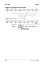
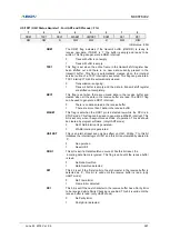
USI1DR (USI1 Data Register: For UART, SPI, and I2C mode) : F5H
7
6
5
4
3
2
1
0
USI1DR7
USI1DR 6
USI1DR 5
USI1DR 4
USI1DR 3
USI1DR 2
USI1DR 1
USI1DR 0
R/W
R/W
R/W
R/W
R/W
R/W
R/W
R/W
Initial value : 00H
USI1DR[7:0]
The USI1 transmit buffer and receive buffer share the same I/O
address with this DATA register. The transmit data buffer is the
destination for data written to the USI1DR register. Reading the
USI1DR register returns the contents of the receive buffer.
Write to this register only when the DRE1 flag is set. In SPI master
mode, the SCK1 clock is generated when data are written to this
register.
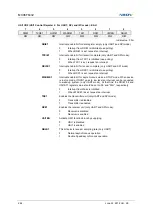
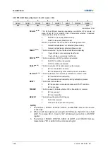
USI1SDHR (USI1 SDA Hold Time Register: For I2C mode) : F4H
7
6
5
4
3
2
1
0
USI1SDHR7
USI1SDHR6
USI1SDHR5
USI1SDHR 4
USI1SDHR 3
USI1SDHR 2
USI1SDHR 1
USI1SDHR 0
R/W
R/W
R/W
R/W
R/W
R/W
R/W
R/W
Initial value : 01H
USI1SDHR[7:0]
The register is used to control SDA1 output timing from the falling
edge of SCL1 in I2C mode.
NOTE) That SDA1 is changed after t
SCLK
X (U2), in
master SDA1 change in the middle of SCL1.
In slave mode, configure this register regarding the frequency of
SCL1 from master.
The SDA1 is changed after tsclk X (U2) in master
mode. So, to insure operation in slave mode, the value
t
SCLK
X (US2) must be smaller than the period of SCL1.
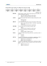
USI1SCHR (USI1 SCL High Period Register: For I2C mode) : F7H
7
6
5
4
3
2
1
0
USI1SCHR7
USI1SCHR6
USI1SCHR5
USI1SCHR 4
USI1SCHR 3
USI1SCHR 2
USI1SCHR 1
USI1SCHR 0
R/W
R/W
R/W
R/W
R/W
R/W
R/W
R/W
Initial value : 3FH
USI1SCHR[7:0]
This register defines the high period of SCL1 when it operates in
I2C master mode.
The base clock is SCLK, the system clock, and the period is
calculated by the formula: t
SCLK
X (4 X US2) where
t
SCLK
is the period of SCLK.
So, the operating frequency of I2C master mode is calculated by the following equation.
f
I2C
=
t
SCLK
X (4 X (US USI1SCHR) + 4)
1
Summary of Contents for MC96F6432 Series
Page 24: ...MC96F6432 24 June 22 2018 Ver 2 9 4 Package Diagram Figure 4 1 48 Pin LQFP 0707 Package...
Page 25: ...MC96F6432 June 22 2018 Ver 2 9 25 Figure 4 2 44 Pin MQFP Package...
Page 26: ...MC96F6432 26 June 22 2018 Ver 2 9 Figure 4 3 32 Pin LQFP Package...
Page 27: ...MC96F6432 June 22 2018 Ver 2 9 27 Figure 4 4 32 Pin SOP Package...
Page 28: ...MC96F6432 28 June 22 2018 Ver 2 9 Figure 4 5 28 Pin SOP Package...


