MC96FM204/FM214
134
April 7, 2016 Ver. 1.8
13. RESET
13.1 Overview
The following is the hardware setting value.
Table 13-1 Reset State
On Chip Hardware
Initial Value
Program Counter (PC)
0000h
Accumulator
00h
Stack Pointer (SP)
07h
Peripheral Clock
On
Control Register
Refer to the Peripheral Registers
13.2 Reset Source
The MC96FM204/FM214 has five types of reset sources. The following is the reset sources.
- External RESETB
- Power ON RESET (POR)
- WDT Overflow Reset (In the case of WDTEN = `1`)
- Low Voltage Reset (In the case of LVREN = `0 `)
- OCD Reset
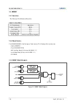
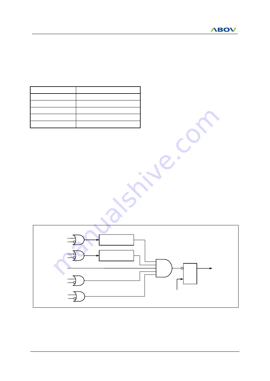
13.3 RESET Block Diagram
Figure 13.1 RESET Block Diagram
WDT RST
WDT RSTEN
Ext RESET
Disable by FUSE
RESET Noise
Canceller
LVR
LVR Enable
RESET Noise
Canceller
POR RST
OCD RST
S Q
R
Internal
Reset
IFBIT
(BIT Overflow)
OCD RSTEN
Summary of Contents for MC96FM204
Page 17: ...MC96FM204 FM214 April 7 2016 Ver 1 8 17 4 Package Diagram Figure 4 1 20 Pin SOP Package ...
Page 18: ...MC96FM204 FM214 18 April 7 2016 Ver 1 8 Figure 4 2 20 Pin TSSOP Package ...
Page 19: ...MC96FM204 FM214 April 7 2016 Ver 1 8 19 Figure 4 3 16 Pin SOP Package ...
Page 20: ...MC96FM204 FM214 20 April 7 2016 Ver 1 8 Figure 4 4 16 Pin TSSOP Package ...


