


MC96FM204/FM214
112
April 7, 2016 Ver. 1.8
11.7 Buzzer Driver
11.7.1 Overview
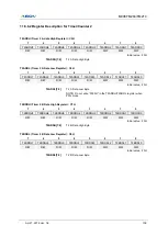
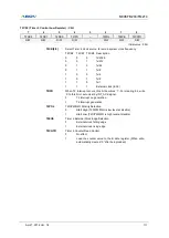
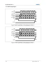
The buzzer consists of 8 bit counter, buzzer data register (BUZDR), and buzzer control register (BUZCR). The
Square Wave (61.035Hz
– 125.0 kHz @8MHz)
is outputted through P12/AN6/CMPO/BUZO pin. The buzzer data
register (BUZDR) controls the buzzer frequency (look at the following expression). In buzzer control register
(BUZCR), BUCK[1:0] selects source clock divided by prescaler.
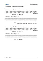
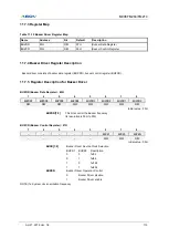
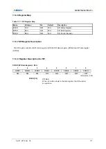
Table 11-9 Buzzer Frequency at 8 MHz
BUZDR[7:0]
Buzzer Frequency (kHz)
BUZCR[2:1]=00
BUZCR[2:1]=01
BUZCR[2:1]=10
BUZCR[2:1]=11
0000_0000
125kHz
62.5kHz
31.25kHz
15.625kHz
0000_0001
62.5kHz
31.25kHz
15.625kHz
7.812kHz
…
…
…
…
…
1111_1101
492.126Hz
246.063Hz
123.031Hz
61.515Hz
1111_1110
490.196Hz
245.098Hz
122.549Hz
61.274Hz
1111_1111
488.281Hz
244.141Hz
122.07Hz
61.035Hz
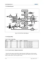
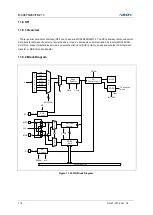
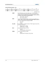
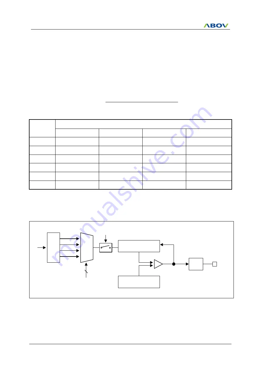
11.7.2 Block Diagram
Pre
scaler
fx
MUX
Counter
fx/32
fx/64
fx/128
fx/256
2
BUCK[1:0]
8-bit Up-Counter
BUZDR
Comparator
F/F
Clear
BUZO
BUZEN
Figure 11.24 Buzzer Driver Block Diagram
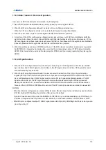
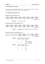
1)
(BUZDR
Ratio
Prescaler
2
Frequency
Oscillator
(Hz)
f
BUZ
Summary of Contents for MC96FM204
Page 17: ...MC96FM204 FM214 April 7 2016 Ver 1 8 17 4 Package Diagram Figure 4 1 20 Pin SOP Package ...
Page 18: ...MC96FM204 FM214 18 April 7 2016 Ver 1 8 Figure 4 2 20 Pin TSSOP Package ...
Page 19: ...MC96FM204 FM214 April 7 2016 Ver 1 8 19 Figure 4 3 16 Pin SOP Package ...
Page 20: ...MC96FM204 FM214 20 April 7 2016 Ver 1 8 Figure 4 4 16 Pin TSSOP Package ...


