MC97F6108A User’s manual
5. I/O ports
39
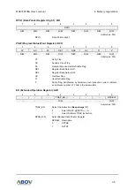
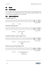
P0DB (P0 De-bounce Enable Register): 2F02H
7
6
5
4
3
2
1
0
P07DB
P06DB
P05DB
P04DB
P03DB
P02DB
P01DB
P00DB
R/W
R/W
R/W
R/W
R/W
R/W
R/W
R/W
Initial value: 00H
P0DB[7:0]
Configure De-bounce of P0 Port
0
Disable
1
Enable
NOTE:
Debounce time of each ports are 1/2/4/8us
NOTES:
1.
If the same level is not detected on enabled pin three or four times in a row at
the sampling clock, the signal is eliminated as noise.
2.
A pulse level should be input for the duration of 3 clock or more to be actually
detected as a valid edge.
3.
The port de-bounce is automatically disabled at stop mode and recovered after
stop mode release.
PSR0 (Port De-bounce Selection Register): 2F48H
7
6
5
4
3
2
1
0
-
-
-
-
PSR03
PSR02
PSR01
PSR00
-
-
-
-
R/W
R/W
R/W
R/W
Initial value: 00H
PSR0[3:2]
External Reset De-bounce Selection Register
PSR03
PSR02
Description
0
0
8us
0
1
16us
1
0
32us
1
1
64us
PSR0[1:0]
Port De-bounce Selection Register
PSR01
PSR00
Description
0
0
1us
0
1
2us
1
0
4us
1
1
8us

