background image


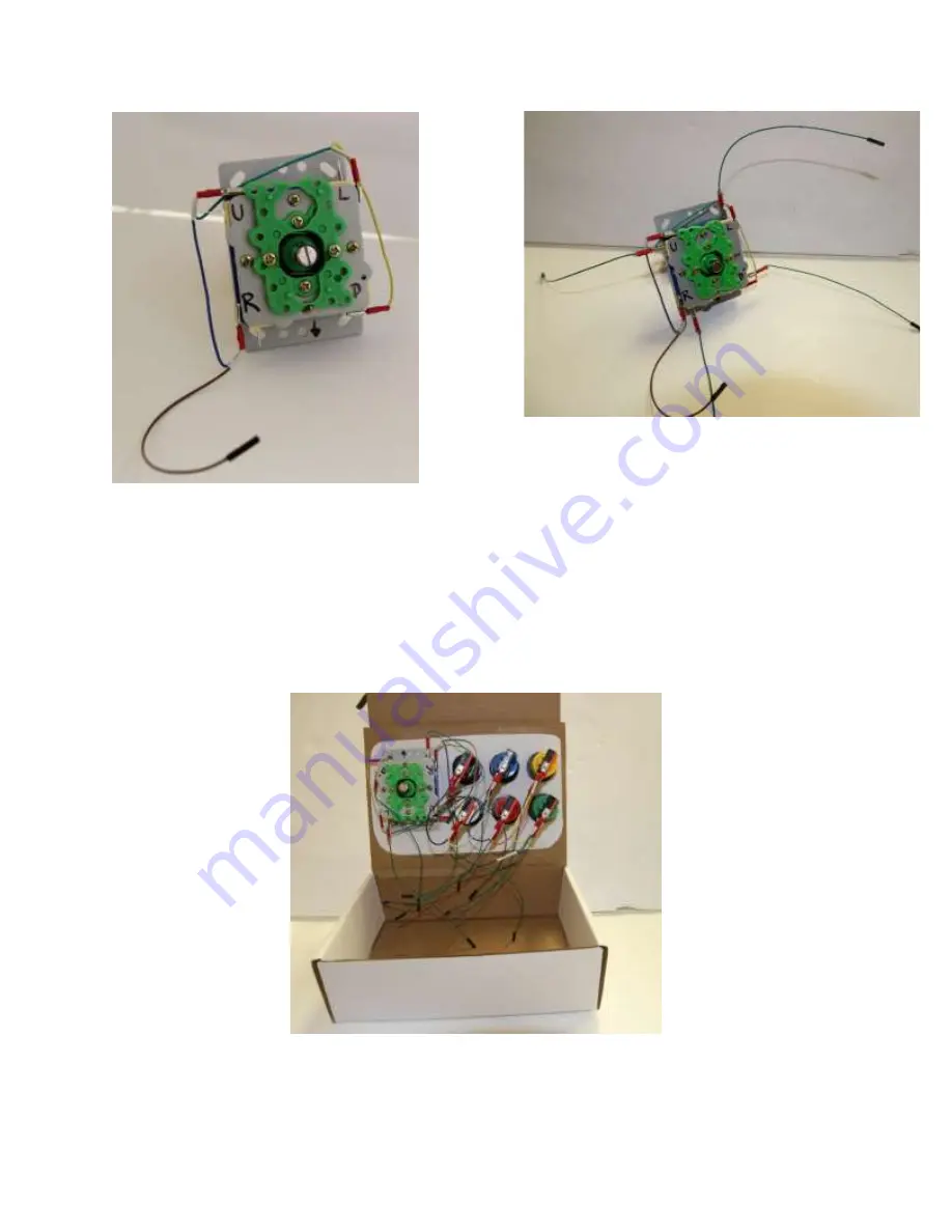
Figure 8 - Joystick Ground Connection 

Play with the joystick and identify each direction of motion with respect to how it will be mounted 
in the box. (Don’t worry if you get this backwards, you can re-assign the directions in the software 
later). Using the joystick cable we made before, connect the common ground cables (you may have 
to bend the tabs a little bit) 

Similarly for the buttons, we now connect the signal wires for the joystick. (You may have to bend 
the tabs a little bit.) 


Figure 9 - Box Wiring 


Figure 7 - Joystick Signal Connection 


Summary of Contents for PI-ARCADE

Page 1: ...PI ARCADE...

Page 2: ...2 3 RASPBERRY PI CONNECTIONS 9 2 3 1 POWER HDMI ETHERNET 9 2 3 4 GPIO 10 3 SOFTWARE 11 3 1 OPERATING SYSTEM DOWNLOAD 11 3 2 REQUIRED SOFTWARE 11 3 2 1 SD FORMATTER 11 3 2 2 DISK IMAGER 11 3 3 SD FORM...

Page 3: ...ation The added bonus is no tokens required to play This guide will show you how to connect the buttons and joystick and turn this simple cardboard box into a realistic game station emulator The kit i...

Page 4: ...Female Jumper 40x12 Wires 793 ADA 100 x Solderless Terminal Lugs 12 1610 100 10 x M3 Mounting Screws FIT0061 1 x SD card loaded with Porta Pi operating system software BBB 16GB 10 1 1 REQUIRED TOOLS R...

Page 5: ...on to wiring In this step we are creating custom cables which can be a little bit tricky The longer the wire the easier it is to connect in the box Figure 2 Signal Wire You will need 10 of these Make...

Page 6: ...Figure 3 Button Ground Wire You will need 1 of these Make sure all are working before proceeding Follow the same steps as above except for stripping and tying 2 wires together before crimping leaving...

Page 7: ...ntinuity at each connection node and the whole length of the cable Figure 5 Button Ground Connection Connect the common grounds of all buttons bottom pin with the cable we made Color coding is a good...

Page 8: ...u get this backwards you can re assign the directions in the software later Using the joystick cable we made before connect the common ground cables you may have to bend the tabs a little bit Similarl...

Page 9: ...ower ethernet and HDMI cables Trace the Raspberry Pi outline with a marker and cut out the ports for the power ethernet and HDMI cables We suggest putting these where they won t interfere with the gam...

Page 10: ...can connect the GPIO General Purpose Input Output pins as should below Figure 14 Raspberry Pi Pinout Figure 15 Raspberry Pi Connection It is a good idea to connect all the wires securely before finall...

Page 11: ...or your Raspberry Pi and to extract and save the files in an ideal location Alternatively you can choose to upload different platforms at this stage The following steps are identical We will go throug...

Page 12: ...tracted the previously downloaded Porta Pi OS Upload the IMG file and press Open button It will then prompt to select the MicroSD card It should automatically find your MicroSD card and skip to the ne...

Page 13: ...13 Figure 16 Controller Template Figure 17 Retro Pi Configuration...

Page 14: ...will not provide any audio Alternatively headphones or speakers may be plugged into the Raspberry Pi s audio jack directly For those who seek the genuine retro gaming experience you can plug the unit...

Page 15: ...ion page for RetroPie Using the arrows and keys access the RETROPIE SETUP Select U Update all installed packages Update time may depend on the size of new additions and could take a few minutes Figure...

Page 16: ...fresh drive Create a new folder called retropie on the SD and insert it into the Raspberry Pi Wait for the flashing light to stop Remove the SD and re insert it into the computer The retropie folder w...

Reviews: