22
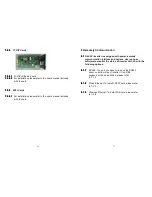
LED Indicators
○
2
Red LED shines steadily to indicate a ground fault or DC input
isolation fault.
○
3
Yellow LED shines steadily to indicate that the utility does not match
the input standard of the inverter (voltage, frequency, etc.).
○
4
Green LED shines steadily when the solar power is greater than sleep
power. It flashes when the solar power is less than sleep power.
Control Keys
○
5
Special functions and log in/out
○
6
Go to next page.
○
7
Confirm change of inverter setting.
○
8
Go to previous page.
23
A
B1
B2
6 Starting the inverter
Before the inverter is started ensure the following:
The wire terminal cover is securely screwed on.
The AC breaker is OFF.
The DC cables (PV strings) are fully connected.
The AC (utility) cable is connected correctly.
6.1
6.1
6.1
6.1
Start-up and operation test
6.1.1
6.1.1
6.1.1
6.1.1
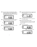
Connect the PV string voltage by switching on the DC switch,
referring to section 4.4.2. Figure 4. The inverter starts
automatically when it senses DC voltage greater than 250
VDC. All of the LEDs will shine. The LCD will display
drawing A.
6.1.2
6.1.2
6.1.2
6.1.2
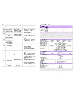
After three seconds the LCD will change from drawing A to
drawings B1 and B2. The green LED will flash to indicate
that the DC input power is less than sleep power. The yellow
LED will shine steadily to indicate the absence of utility
power.

