background image


38 

9 Inverter status diagnostics and repair 

The PV Inverter is equipped with a self diagnostic system that automatically 

identifies  many  possible  operational  issues  and  displays  information  about  them 
on  the  LCD.  Therefore  it  is  possible  to  quickly  isolate  technical  problems  and  to 
distinguish  between  service  codes  related  to  the  installation  and  service  codes 
which  are  internal  to  the  inverter.  Whenever  the  diagnostic  system  identifies  a 
particular issue the respective service code is displayed on the LCD. 

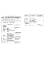
Table 2. Inverter error codes and descriptions 

LCD 

Designation 

Description 

Repair 

Er00 

DC_BUS 
pre-charge failure 

The  inverter  is  in  the  soft  start 
procedure,  but  the  DC  bus  cannot 
reach  and  maintain  anticipative 
charging voltage 

1. Disconnect ALL PV (+) and 

PV (-) cables. 

2. Wait for a few seconds. 
3. After the LCD switches off 

reconnect and check again. 

4. If the error code keeps 

recurring contact your local 
distributor. 

Er07 

DC_BUS 
over-voltage 

The DC bus voltage is lower or 
higher than expected. 

Er08 

DC_BUS 
under-voltage 

Er17 

EEPROM ERROR 
on the control 
board 

EEPROM data is wrong. 

Er22 

Output relay failure 

The inverter’s output relay is 
abnormal. 

Er24 

Output current 
sense failure 

The inverter’s output current fails to 
be detected. 

Er25 

BOOSTER_A 
over-current 

Over-current on the DC side. This 
fault code is displayed if the current 
in the DC network is larger than 
specified. 

Er26 

BOOSTER_B   
over-current 

Er06 

EPO 

Inverter enters into EPO mode 
(Emergency Power Off). 

1. Remove the short circuit 

occurring at the EPO terminal. 

2. If the error code keeps 

recurring contact your local 
distributor. 

Er09 

Inverter output 
over-current 

Over-current on the AC side. This 
fault code is displayed if the current 
in the AC network is larger than 
specified. 

1. Turn off the AC breaker, then 

check the peripheral AC 
system configuration and the 
grid conditions. 

2. If the error code keeps 

recurring contact your local 
distributor for help. 

Er11 

Inverter overload 

Overload on the AC side. This fault 
code is displayed if the load in the 
AC network is larger than specified. 

Er13 

Inverter short 
circuit 

Short circuit on the AC side 

Er14 

Inverter PLL failure 

The phase of the inverter cannot 
synchronize with the utility. 

Er29 

Inverter output DC 
current over spec. 

The DC component of the electricity 
fed into the grid is larger than the 
permissible range. 

Er10 

Inverter Over 
temperature 

The internal temperature is too 
high. 

1. Try to reduce the ambient 

temperature. 

2. Move the inverter to a cooler 


39 

Er18 

Heat sink over 
temperature 

The heat sink temperature is too 
high. 

place. 

3. If the error code keeps 

recurring contact your local 
distributor for help. 

Er02 

Slave MCU failure 

Slave MCU failure 

1. If the error code keeps 

recurring contact your local 
distributor for help. 

Er05 

Watch Dog 

DSP Watch Dog   

Er12 

Charger fault 

DC BUS    pre-charge failure 

Er15 

Slave Info fail 

The data check failed between two 
MCUs. 

Er27 

Booster Short 
Circuit 

Short-current on the DC side. 

Er41 

Boost A Sense fault 

Current sensor fault on the stringA 
of DC side. 

Er42 

Boost B Sense 
fault 

Current sensor fault on the stringB 
of DC side. 

Er43 

Out Balance Sense 
fault 

Current sensor fault on the AC side. 

Er37 

Fan fault 

A fan is not rotating. 

1. Check the fans. 
2. If the error code keeps 

recurring contact your local 
distributor for help. 


Summary of Contents for EnerSolis ES 12000

Page 1: ...ng 8 4 2 Installation requirements 9 4 3 Mounting the unit 11 4 4 Electrical installation 14 5 Front display panel 21 6 Starting the inverter 23 6 1 Start up and operation test 23 6 2 Checking values...

Page 2: ...tructions for the ES 6000 ES 8000 ES 10000 ES 12000 that must be followed during installation and maintenance of the inverter Housing Only qualified installers are authorized to open the connection ar...

Page 3: ...voltage when temperature is low and sunlight level remains unchanged At 4 F 20 C the open circuit voltage of the PV modules must never exceed 1 000 V The data sheet of the solar module will include th...

Page 4: ...External features 1 LCD and LED display Shows operation information and status 2 Solar array input plug and play connectors for the solar modules 3 Standard communication ports EPO RS 232 and RS 485...

Page 5: ...oning paper 9 4 2 4 2 4 2 4 2 Installation requirements The PV inverter is heavy Take this weight into account when choosing the installation site and method of installation To ensure proper operation...

Page 6: ...nstallation site ensure that there is enough space for heat dissipation Under normal conditions the following clearance guidelines should be applied 11 4 3 4 3 4 3 4 3 Mounting the unit For vertical i...

Page 7: ...kplane on the wall Step 2 Screw the nut on the sleeve without fastening Step 3 Hang the PV inverter on the backplane Make sure that it holds the inverter unit firm and securelyFinally fastening the nu...

Page 8: ...PV inverter are shown in Figure 1 Figure 1 15 4 4 1 4 4 1 4 4 1 4 4 1 Connecting to the grid AC utility Caution Before connecting to Grid AC utility please install a separate circuit breaker between...

Page 9: ...earthed before operating the PV inverter Suggested AC cable width Model Area mm 2 AWG no ES 6000 2 1 14 ES 8000 2 1 14 ES 10000 3 5 12 ES 12000 3 5 12 17 4 4 2 4 4 2 4 4 2 4 4 2 Status identification...

Page 10: ...00 VDC under any conditions Voltage over 1 000 VDC will damage the inverter 2 Do not exceed the maximum array short circuit current rating marked on the inverter 3 To harvest maximum energy from your...

Page 11: ...panels in String A need not equal the number in String B For a single PV string enter settings mode and configure for parallel operation 21 5 Front display panel Symbols on the LCD 1 LCD Symbol Descri...

Page 12: ...rted ensure the following The wire terminal cover is securely screwed on The AC breaker is OFF The DC cables PV strings are fully connected The AC utility cable is connected correctly 6 1 6 1 6 1 6 1...

Page 13: ...ll still flash 6 1 5 6 1 5 6 1 5 6 1 5 After ten seconds if the inverter s AC soft start is successful the LCD will display drawing E 25 F 6 1 6 6 1 6 6 1 6 6 1 6 If the inverter encounters a problem...

Page 14: ...7 Output voltage A of the inverter utility voltage I J K L M 27 6 2 8 6 2 8 6 2 8 6 2 8 Output voltage B of the inverter utility voltage 6 2 9 6 2 9 6 2 9 6 2 9 Output voltage C of the inverter utilit...

Page 15: ...ter is working normally Whenever the PV array voltage is within range 300 1 000 VDC the PV inverter passes power to the grid as generated by the PV array In normal mode the green LED shines to indicat...

Page 16: ...ured as follows Baud Rate 9600 bps Data Length 8 bits Stop Bit 1 Parity None Pin 2 RS 232 Rx Pin 3 RS 232 Tx Pin 5 Ground 1 2 3 4 5 6 7 8 9 31 RS 485 pin assignments are as follows PIN 3 485 GND PIN 4...

Page 17: ...e that the AC breaker or switch cannot be unintentionally closed during installation and commissioning works Unscrew the two screws and remove the cover Insert the communication card into the slot 33...

Page 18: ...DCE B card 7 2 4 1 7 2 4 1 7 2 4 1 7 2 4 1 Pin assignments of the 10 pin terminal 1 2 3 4 5 6 7 8 Pin 1 Utility voltage is abnormal Pin 2 PV array voltage is normal Pin 3 PV array voltage is abnormal...

Page 19: ...motely Communication 8 1 8 1 8 1 8 1 Grid PV Inverter is equipped with power remotely communication interface and options User can use software to monitor the status of inverter with PC with the follo...

Page 20: ...ror code keeps recurring contact your local distributor Er09 Inverter output over current Over current on the AC side This fault code is displayed if the current in the AC network is larger than speci...

Page 21: ...tributor for help AL11 Isolation fault The impedance between PV and PV and ground is less than 1 M 1 Disconnect ALL PV and PV cables 2 Check the impedance between PV and PV and ground The impedance mu...

Page 22: ...olation fault Islanding operation detection Passive Voltage phase jump detection Active Reactive power control Over temperature Downgraded output power Certification On Grid Performance VDE 0126 1 1 V...

Reviews: