

ABtUS
SINGAPORE PTE LTD
www.abtussingapore.com
** For detail, updated Command Code and Application Software, please visit and download from www.abtussingapore.com
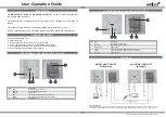
HDMI over CAT-5
Wall Plate Extender
Model:
MU-CATHD11T/2-06-ST
(Transmitter)
Model:
MU-CATHD11R/2-06-ST
(Receiver)
SPECIFICATION
Revision 06102015
MU-CATHD11T/2-06-ST
MU-CATHD11R/2-06-ST
Input:
1×HDMI
2×RJ45 + 1×3.5mm
Output:
2×RJ45 + 1x 3.5mm
1×HDMI
HDMI Source Control:
Controllable via IR pass-through from RX to TX
IR Remote Control:
Electro-optical characteristics:
τ
= 25º /
Carrier frequency:
20~60kHz
HDMI Connector:
Type A (19-pin female)
RJ45 Connector:
WE/SS 8P8C
3.5MM Connector:
3.5mm jack for IR emitter
3.5mm jack for IR receiver
ROTARY CONTROL:
None EQ for signal equalization
HDMI COMPLIANCE:
HDMI Deep Color
HDCP COMPLIANCE:
Yes
VIDEO BANDWIDTH:
Single-link 225MHz (6.75Gbps)
VIDEO SUPPORT:
480i / 480p / 720p / 1080i / 1080p60 24/30/36-bit color
AUDIO SUPPORT:
Surround sound (up to 7.1ch) or stereo digital audio
HDMI over UTP Transmission (24-BIT):
Full HD (1080p)-40m (130ft) [CAT-5]
HD (720p/1080i)-50m (165ft) [CAT-5]
HDMI Equalizartion:
N/A 8-level digital rotary control
Input TMDS Signal:
1.2 Volts (peak-to-peak)
Input DDC Signal:
5 Volts (peak-to-peak, TTL)
ESD Protection:
[1] Human body — ±19kV air-gap discharge
& ±12kV contact discharge
[2] Core chipset — ±8kV
PCB Stack-Up:
PCB stack-up 4-layer board
(impedance control — differential 100
Ω
; single 50
Ω
)
Fixedness:
Wall plate mounting
Power Supply:
12V 1A DC at either TX or RX
Power Consumption:
1 Watt (max)
Operation Temperature:
0~40°C [32~104°F]
Storage Temperature:
-20~60°C [-4~140°F]
Relative Humidity:
20~90% RH (no condensation]
Housing:
Metal enclosure
Gross Dimensions:
95mm × 190mm × 80mm
Gross Weight:
620 g
* Specifi cations are subject to changes without notice.
Caution :
Always ensure that the DDC output on the transmitters connected to the
DDC input of the receiver before connecting the power supply. In no circumstances
should a cable be connected on a DDC port at one end and a TMDS port at the
other. Connecting a cable on DDC to TMDS will permanently damage the product.


