390229 5
/0
6
ABUS - Das gute Gefühl der Sicherheit
www.abus.com
Abb. / fig.
schéma
afb. / ill.
4
D
V. Montageanleitung:
Wichtige Hinweise:
• Vor der Montage prüfen Sie bitte die Einstellung des Fensters bzw.
der Fenstertür. Stellen Sie sicher, dass sich das Fenster/die Fenstertür
einwandfrei öffnen und schließen lässt.
• Messen Sie auch nach, ob die in Abb. 1 angegebenen Mindestmaße
an Ihrem Fenster/ Ihrer Fenstertür vorhanden sind.
• Die Bohrlochtiefen bzw. die Schraubenlängen müssen auf die ört-
lichen Gegebenheiten abgestimmt werden.
• Austreten des Bohrers bzw. der Schrauben auf der Rückseite
vermeiden! Ggf. mit Bohranschlag arbeiten oder die vorhandenen
Schrauben kürzen.
• Beim Bohren keine beweglichen Teile, Dichtungen oder Glasscheiben
verletzen.
Montage:
Montage ab 14 mm Falzstärke
1.
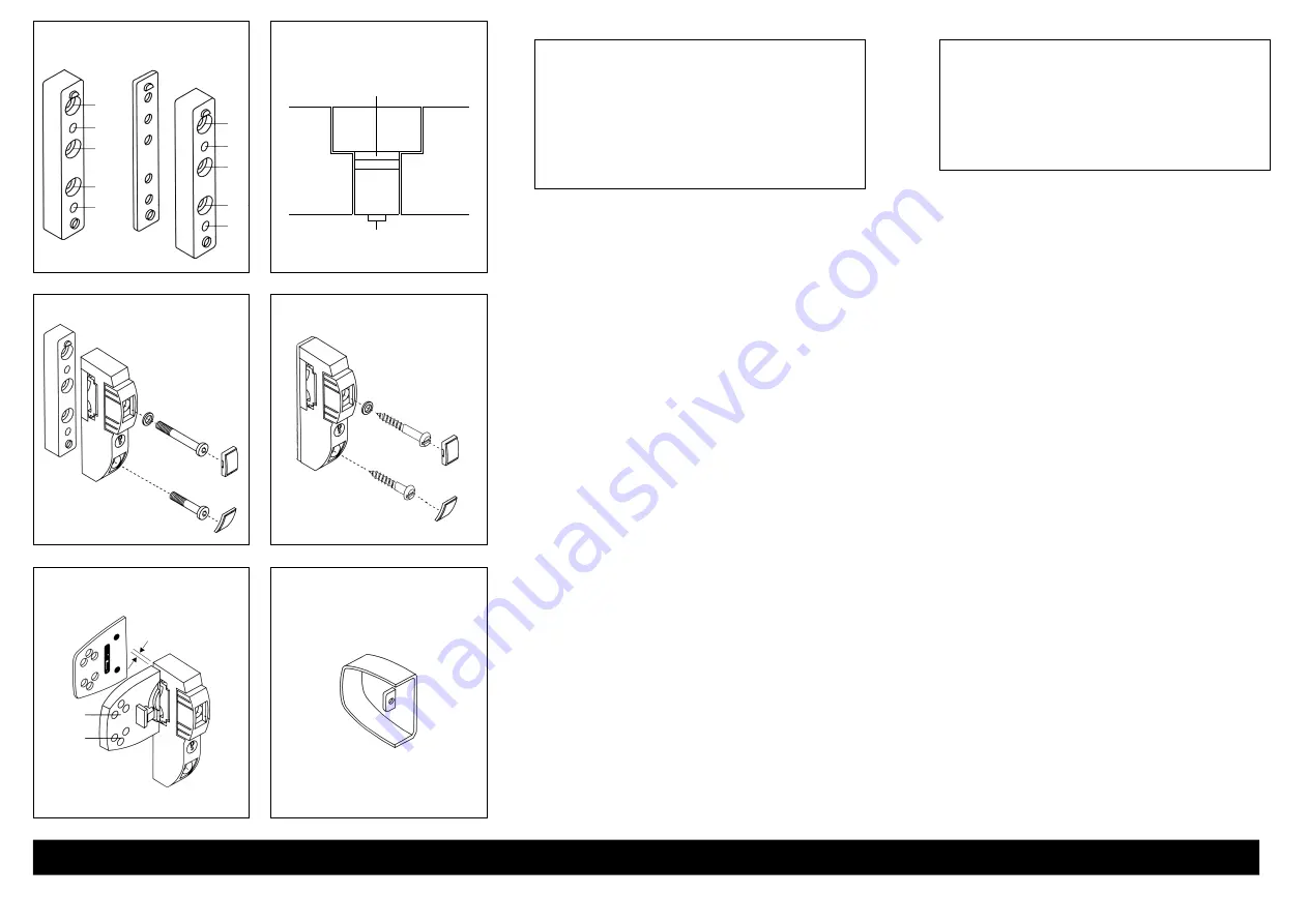
Anschraubleiste (3) in gewünschter Höhe (halbe Höhe zwischen Fenster-
griff und Unterkante des Fensterflügels) mittig zwischen den Fensterflügeln
anhalten. Halbmondnocken nach oben. Bohrungen (a) anzeichnen
(Abb. 4) und vorbohren (s. Bohrtabelle).
2. Anschraubleiste (3) mit Unterlagen (6) soweit unterfüttern,
bis Oberkante Anschraubleiste (3) und Oberkante Fensterflügel
auf einer Ebene liegen (Abb. 4a + 5). Bei Falzdickenunterschiede
der beiden Fensterflügel die Oberkante des dickeren Falzes auswählen.
Anschraubleiste (3) mit Unterlagen (6) mit den Schrauben 5,5 x 60 mm
anschrauben (Bohrlöcher a).
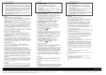
3. Schraubabdeckungen (4) des Schlosskastens (1) von unten ausstoßen.
Schlosskasten (1) mit Schrauben M6 x 30 mm und M6 x 45 mm mit
U-Scheibe auf die Anschraubleiste (3) schrauben (Abb. 6).
Montage von 0 –13 mm Falzstärke
1. Anschraubleiste (3) in gewünschter Höhe (halbe Höhe zwischen Fenster-
griff und Unterkante des Fensterflügels) mittig zwischen den Fensterflügeln
anhalten. Halbmondnocken nach oben. Bohrungen (b) anzeichnen
(Abb. 4) und vorbohren (s Bohrtabelle).
2. Schraubenabdeckungen (4) des Schlosskastens (1) von unten ausstoßen.
Schlosskasten (1) je nach Falzstärke mit den Unterlagen (6) unterfüttern
(Halbmondnocken nach oben). Bei Falzdickenunterschiede der beiden
Fensterflügel die Oberkante des dickeren Falzes auswählen. Mit Schrauben
5,5 x 60 mm und 5,5 x 80 mm mit U-Scheibe anschrauben (Abb. 7).
Montage der Schließplatten
1. Abdeckkappen (5) mit Schraubendreher von den Schließplatten (2) lösen.
Hierbei von der offenen Seite mit dem Schraubendreher zwischen Metall-
nase und Haube ansetzen und die Teile auseinander drücken.
2. Schließplatten (2) (Abb. 8) auf die Fensterflügel legen und im Abstand
von 1 mm an den Schlosskasten (1) halten. Bei Falzdickenunterschiede
der beiden Fensterflügel Schließplatten für den dünneren Falz mit Unter-
lagen ausgleichen. Riegelfunktion prüfen. Schlüssel einstecken und um
90
°
drehen. Je 1 der 3 Bohrlöcher „c“ oben und unten anzeichnen
und vorbohren (s. Bohrtabelle). Schließplatten (2) mit den Schrauben
5,5 x 50 mm anschrauben.
3. Funktion des Schlosses überprüfen. Schraubenabdeckungen (4)
(Abb. 6 + 7) aufdrücken. Abdeckkappen (5) auf Schließplatten (2)
aufdrücken (Abb. 8 + 9).
Hinweis:
Nach dem Entriegeln durch den Schlüssel ist der Drehknopf unbedingt
senkrecht zu stellen und der Schlüssel abzuziehen, da der Drehknopf
sonst nicht blockiert ist.
ABUS empfiehlt zur Sicherung der Scharnierseite den Einbau der
ABUS-Scharnierseiten-Sicherungen FAS 97 oder FAS 101.
VI. Bedienung
Die Verriegelung des Schlosses erfolgt ohne Schlüssel durch
1
/
4
- Drehung
des Kunststoffknopfes. Der Mechanismus rastet hörbar ein.
Entriegelung: Schlüssel einstecken und um 90
°
drehen.
Drehknopf senkrecht stellen, Schlüssel zurückdrehen und abziehen.
G
V. Assembly Instructions:
Important notes:
• Prior to assembly, please check the adjustment of the window
or French window. Make sure that the window/French window
can be opened and closed correctly.
• Check that the min. dimensions shown in fig. 1 apply to your
window or French window.
• The drill hole depths or screw lengths must be adjusted to local
conditions.
• Avoid the drill bit or screws coming out on the rear sides!
If necessary, use a bit stop or cut the screws to size.
• Do not damage any moving parts, seals or glass panes when drilling.
Assembly:
Rebate 14 mm
1. Hold screw-on rail (3) at desired height (half height between window
handle and lower edge of the window casement) centre between the
window casements. Crescent cams facing up. Mark holes (a) (fig. 4)
and drill (see Drilling Table).
2. Place spacers (6) under screw-on rail (3) until upper edge of screw-on
rail (3) and upper edge of window casement are flush (fig. 4a + 5).
If the casements have different rebate sizes, select the upper edge of
the thicker rebate. Fasten screw-on rail (3) with spacers (6) with screws
5.5 x 60 mm (drill holes a).
3. Eject screw covers (4) of the lock case (1) from below. Fasten lock case (1)
with screws M 6 x 30 and M 6x 45 with washer to the screw-on rail (3)
(fig. 6).
Rebate 0 –13 mm
1. Hold screw-on rail (3) at desired height (half height between window
handle and lower edge of the window casement) centre between the
window casements. Crescent cam facing up. Mark holes (b) (fig. 4)
and drill (see Drilling Table).
2. Eject screw covers (4) of the lock case (1) from below. Back lock case (1)
with spacers (6) depending on rebate size (crescent cams facing up).
If the casements have different rebate sizes, select the upper edge of
the thicker rebate. Fasten with screws 5.5 x 60 mm and 5.5 x 80 mm
with washer (fig. 7).
Assembly of the striking plates
1. Remove covers (5) from the striking plates (2) using a screwdriver.
Apply the screwdriver from the open side between metal nose and hood
and press the parts apart.
2. Place the striking plates (2) (fig. 8) onto the window casements and hold
them 1 mm away from the lock case (1). If the rebates of the casements
have different sizes, equalise the striking plates for the thinner rebate
using spacers. Check bolt function. Insert key and turn 90
°
. Mark one
of the three holes “c” each top and bottom and drill (see Drilling Table).
Fasten striking plates (2) with screws 5.5 x 50 mm.
3. Check the function of the lock. Press on the screw covers (4) (fig. 6 + 7).
Press the covers (5) onto the striking plates (2) (fig. 8 + 9).
Note:
After unlocking with the key, make sure to place the handle in vertical
position and draw the key, because otherwise the handle will not be
blocked.
ABUS recommends to install ABUS hinge side security devices FAS 97 or
FAS 101 to protect the hinge side.
VI. Operation
The lock is latched without key with a quarter turn of the plastic handle.
The mechanism locks audibly. To unlock, insert key and turn 90
°
.
Place handle upright, turn key back and draw key out.
D
Technische Änderungen vorbehalten. Für Irrtümer und Druckfehler keine Haftung. ABUS © 2006
G
Subject to technical alterations. No liability for mistakes and printing errors. ABUS © 2006
Abb. / fig. / schéma / afb. / ill.
5
Abb. / fig. / schéma / afb. / ill.
6
Abb. / fig. / schéma / afb. / ill.
7
Abb. / fig. / schéma / afb. / ill.
8
Abb. / fig. / schéma / afb. / ill.
9
1 mm
c
a
b
a
a
b
a
b
a
a
b
Abb. / fig.
schéma
afb. / ill.
4 a
Kunststoffunterlage
Spacers / Cales de respectivement
Opvulplaatjes / Spessori
Fensterflügel
Window
Cadre
Raamvleugel
Battente
Anschraubleiste
Screw-on rail / Barre de vissage
Montageplaat / Listello di montaggio
Fensterflügel
Window
Cadre
Raamvleugel
Battente


