27
English
5. Mounting/installation
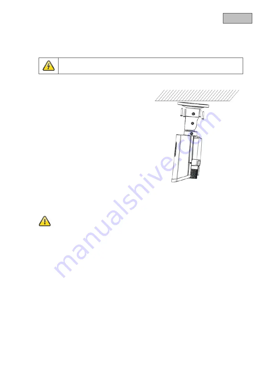
5.1. Mounting the camera
IMPORTANT!
The camera must be disconnected from the power supply during installation.
Use the accompanying drilling template for drilling
the mounting holes. An opening is provided on
the base plate of the mount for cabling at the
side. Use screw anchors and screws that are
appropriate to the surface to fix the camera in
place.
Cabling can be at the side or hidden in the ceiling
or wall.
Orientation of the camera, as described below, can now be performed. At this point, an analogue test
monitor may be connected to the camera (for test purposes only, can be activated in place of the HD-TVI
signal on 720p models). The monitor is connected either to the connecting cable on the camera or to the
underside of the camera using the supplied adapter.
Tighten the fixing screws again after orienting the camera.
Summary of Contents for HDCC61510
Page 105: ...105 HDCC61510 04 2015...
Page 107: ...107 CE IP66...
Page 108: ...108 1 2 3 1 2 3...
Page 109: ...109...
Page 111: ...111 1 HD HD TVI 2 HD TVI Vario 3 CCTV 500 Vario 2 8 12 1 3 DNR DWDR IP66...
Page 112: ...112 4 1 2 3 4 5 6 BNC 7 HD TVI BNC TVI 8 2 12 24 9 HDCC61510 HD TVI 10 OSD 11 2...
Page 113: ...113 5 5 1 720p HD TVI...
Page 114: ...114 5 2 1 2 3 5 3 12 24 5 4 HD TVI RG59 RG6 BNC TVI 500 RG6 300 RG59 CVBS RG59 RG6 100...
Page 115: ...115 HD TVI 6 5 5 HD TVI HD TVI TVI HD TVI...
Page 120: ...120 RESET RESET SAVE EXIT SAVE OSD EXIT OSD...
Page 121: ...121 7 7 1 7 2 8 2002 96...

