30
English
5.5. Switching between HD-TVI and analogue video signal
A switch on the PCB of the camera module
switches the video signals of both video outputs
(at the external cable and at the internal 2-pin
connection) between HD-TVI or PAL analogue
signal.
After installation and orientation of the
camera module, move the switch to the 'TVI”
position to activate the HD-TVI output.
5.6. Installation on the wall mount
1. First drill the four holes in the wall to attach
the wall mount to the wall.
2. Use appropriate screw anchors and screws
to attach the wall mount to the wall.
3. Screw the round adapter plate on to the wall
mount. Secure the adapter using a side
fixing screw.
4. Attach the installation adapter to the wall
mount.
5. Run all cables through the wall mount and
connect them correctly to the camera
module.
6. You can now carry out the subsequent steps
as previously described in the section on
installation.
The appropriate
TVAC31320
wall mount is
required for the installation. This is not included in
the scope of delivery of the camera.
5.7 Installation on a suspended ceiling
The following installation data must be observed:
Installation depth (min.): 50 mm
Diameter of camera insert:
min. 145 mm (max. 152 mm)
Diameter for fixings: 10 mm
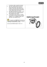
1.
First, create an opening of min. 145 mm to
max. 152 mm at the desired location in the
suspended ceiling.
2.
Glue the drilling template to the opening in
the ceiling in a central position.
3.
Drill three holes with a diameter of approx.
10 mm in the places marked.
4.
Screw the three long metric screws supplied
through the three outer fixing holes in the
ceiling recessing ring.
5.
Then screw the three spreading clamps on

