background image


6

3.   Anschlüsse und Funktionen 

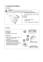
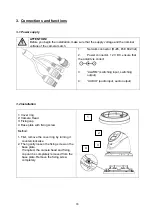
3.1 Anschlüsse 


ACHTUNG! 

Bevor Sie mit der Installation beginnen, stellen Sie sicher, dass die 
Versorgungsspannung und die Nennspannung der Kamera übereinstimmen. 

1: 

Netzwerkanschluss (RJ45, 

PoE 802.3af

 
2: 

Spannungsanschluss, 12 VDC, Polarität 

ist zu beachten 


3: 

„ALARM“ (Schalteingang, 
Schaltausgang) 

 
4: 

„AUDIO“ (Audioeingang, Audioausgang) 


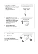
3.2 Installation 


1:  Abdeckring 
2:  Kamerakopf 
3:  Fixierkappe 
4:  Bodenplatte mit Fixierschraube 
 
Vorgehensweise: 


1.  Entfernen Sie als Erstes den Abdeckring 

durch Drehen entgegen dem 
Uhrzeigersinn. 

2.  Lösen Sie anschließend leicht die 

Fixierschraube an der Bodenplatte. 
Bei Bedarf können Kamerakopf und 
Fixierkappe komplett von der Bodenplatte 
entfernt werden. Entfernen Sie die 
Fixierschraube dazu vollständig. 


1

2

3

4

Summary of Contents for IPCS58571A

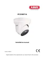
Page 1: ...IPCS58571A D Installationsanleitung uk Installation manual Version 01 2023...

Page 2: ...gen Inhaber Alle Rechte vorbehalten Bei Fragen wenden Sie sich an Ihren Facherrichter oder Fachhandelspartner Haftungsausschluss Diese Bedienungsanleitung wurde mit gr ter Sorgfalt erstellt Sollten Ih...

Page 3: ...t achtlos liegen Plastikfolien t ten Styroporteile usw k nnten f r Kinder zu einem gef hrlichen Spielzeug werden Die Video berwachungskamera darf aufgrund verschluckbarer Kleinteile aus Sicherheitsgr...

Page 4: ...RSTELLEN DER EINSTELLUNGEN RESET 8 3 5 SD KARTEN EINSCHUB 8 3 6 VERWENDUNG DES STECKERSCHUTZES 9 3 7 INSTALLATION MIT WANDHALTERUNG 9 3 8 INSTALLATION MIT INSTALLATIONSBOX 10 3 9 SCHALTEINGANG SCHALTA...

Page 5: ...e das Produkt in Betrieb nehmen Die Bedienungsanleitung enth lt wichtige Informationen f r Montage und Bedienung 2 Symbolerkl rung Das Symbol mit dem Blitz im Dreieck wird verwendet wenn Gefahr f r di...

Page 6: ...n 3 ALARM Schalteingang Schaltausgang 4 AUDIO Audioeingang Audioausgang 3 2 Installation 1 Abdeckring 2 Kamerakopf 3 Fixierkappe 4 Bodenplatte mit Fixierschraube Vorgehensweise 1 Entfernen Sie als Ers...

Page 7: ...latte in den Untergrund oder verwenden Sie den optionalen Geh useausbruch an der Bodenplatte f r eine seitliche Kabelf hrung das Kabel muss in diesem Fall vor Installation der Bodenplatte seitlich ver...

Page 8: ...gedr ckt 3 Verbinden Sie nun die Spannungsversorgung mit der Kamera ber 2 Pin Spannungsversorgung oder Power over Ethernet und halten Sie die Taste Reset f r weitere 30 Sekunden gedr ckt 3 5 SD Karte...

Page 9: ...endung des Steckerschutzes ist in jedem Fall der Ethernetstecker zu crimpen Eine Verwendung mit vorkonfektionierten Ethernetkabeln mit Steckern ist nicht m glich 3 7 Installation mit Wandhalterung F r...

Page 10: ...rzunehmen bitte ggf Alternativmodell ber die Produktsuche unter www abus com recherchieren 3 9 Schalteingang Schaltausgang Die maximalen Belastungswerte sind zu beachten andernfalls kann die Kamera ir...

Page 11: ...tfeld schlecht reflektierend ist oder sich kein Objekt in der max Ausleuchtungsreichweite befindet so kann die Helligkeit des Videobildes in der Nacht zu gering sein Dies hat eine schlechte Verwertbar...

Page 12: ...r Sie wartungsfrei Es sind keinerlei f r Sie zu berpr fende oder zu wartende Bestandteile im Inneren des Produkts ffnen Sie es niemals 4 2 Reinigung Reinigen Sie das Produkt mit einem sauberen trocken...

Page 13: ...IPCS58571A Installation manual Version 01 2023 English translation of the original German user manual Retain for future reference...

Page 14: ...nding owner All rights reserved If you have any questions please contact your specialist installation contractor or specialist dealer Disclaimer This user manual has been produced with the greatest of...

Page 15: ...sheeting polystyrene packaging etc can pose a danger to children if played with The video surveillance camera contains small parts which could be swallowed and must be kept out of the reach of childre...

Page 16: ...RA 19 3 4 RESET TO FACTORY DEFAULT 20 3 5 SD CARD SLOT 20 3 6 USAGE OF CONNECTOR COVER 21 3 7 INSTALLATION ON WALL MOUNT 21 3 8 INSTALLATION ON JUNCTION BOX 22 3 9 SWITCHING INPUT OUTPUT 22 3 10 AUDIO...

Page 17: ...he product into operation The user guide contains important information on installation and operation 2 Explanation of symbols The triangular high voltage symbol is used to warn of the risk of injury...

Page 18: ...t the polarity is correct 3 ALARM switching input switching output 4 AUDIO audio input audio output 3 2 Installation 1 Cover ring 2 Camera Head 3 Fixing cap 4 Base plate with fixing screw Method 1 Fir...

Page 19: ...n the middle of the floor panel in the ground or use the optional box hole on the floor panel for side cable routing in this case the cable must be routed sideways before installing the floor panel 5...

Page 20: ...button on the camera 3 Now connect the power supply to the camera via 2 pin power supply or Power over Ethernet and press the Reset button for another 30 seconds 3 5 SD Card slot To install the micro...

Page 21: ...and moisture When using the connector protection the Ethernet connector must always be crimped Use with pre assembled Ethernet cables with plugs is not possible 3 7 Installation on Wall mount The wal...

Page 22: ...cessary please research alternative model using the product search at www abus com 3 9 Switching input output The maximum load values must be observed otherwise the camera may be irreparably damaged D...

Page 23: ...dings in the camera s field of view are poorly reflective or if there is no object within the maximum illumination range the brightness of the video image may be too low at night This results in poor...

Page 24: ...n Please note You do not need to perform any maintenance on the product There are no components requiring servicing or checking inside the product Never open it 4 2 Cleaning Clean the product with a c...

Reviews: