41
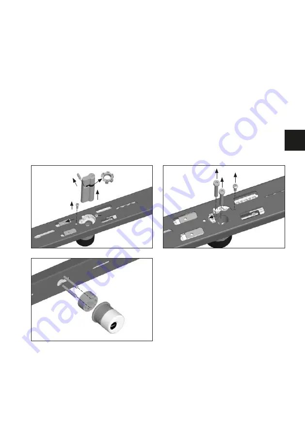
2. Lock door bars and remove the door cylinder in the specified order according to Fig. 5.
3. Change the grub screw and the gear-wheels clip of the standard door cylinder to the new
door cylinder, according to Fig. 5. The grub screw must protrude at the same distance on
both sides.
If the cylinder length does not change, continue to point 8.
4. Unscrew the loosened screw 1 (Fig. 6), move the gear-wheel housing in the direction of
the arrow. Unscrew the cylinder protection‘s screws located beneath (Fig. 6).
5. Remove the cylinder protection according to Fig. 7 and place additional spacer disc/s
(Tab. 1.) between the cylinder protection and the lock body. Tighten with screws (Tab. 1).
6. Pull the gear-wheel housing into the old fitting position again (Fig. 6) and fix loosely
with screw 1.
7. Push toothed gear racks in the direction of the arrow (fig. 8) until they stop, whereby
the upper ones must be pushed back by one tooth.
8. Reinstall the door cylinder in the reverse order (Fig. 5). If the indentations do not
correspond, loosen the stop screws 6. and 7. (Fig. 8), pull both door bars out until
the gear-wheels do correspond and complete the installation of the door cylinder.
Set the key pull-off position (see the instructions below).
2.
3.
1.
3.
Fig. 6
Fig. 5
3.
5.
6.
4.
2.
1. loosen
Fig. 7
GB
Summary of Contents for PR2700
Page 18: ...18 Notizen ...
Page 19: ...Notice de montage et d utilisation Barre transversale blindée PR2700 FR PR2700 www abus com ...
Page 35: ...35 Fitting and operating instructions Reinforced door bar PR2700 GB PR2700 www abus com ...
Page 51: ...51 Montage en gebruikshandleiding Deurbalk PR2700 NL PR2700 www abus com ...
Page 67: ...67 Notities NL ...


