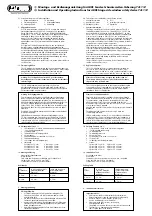
für
Schrauben
Ø
In Holz und Kunststoff
ohne
Metalleinlage
Bohrer Ø
In Alu und Kunststoff
mit
Metalleinlage
Bohrer Ø
3,5 mm
4,0 mm
4,0 mm
4,5 mm
4,8 mm
5,5 mm
Bohrtabelle
D
Diese Anleitung ist wie folgt untergliedert:
I.
Allgemeine Hinweise
IV. Werkzeug
II. Einsatzmöglichkeit
V. Montageanleitung
III. Packungsinhalt
VI. Bedienung
I.
Allgemeine Hinweise
Die Tür-Scharnierseiten-Sicherung TAS 112 ist nach den strengen
Prüfanforderungen der DIN 18 104-1 und VdS 2536 anerkannt.
Durch DIN Certco ist TAS 112 zertifiziert „EINBRUCHHEMMEND
DIN-geprüft“. TAS 112 bietet zusätzlich Schutz gegen unberechtigtes
Eindringen in Räume. Gemäß DIN 18 104-1 wird empfohlen,
dass pro 1 Meter Türhöhe rechts und links jeweils eine Zusatz-
sicherung montiert wird (wobei 1 Sicherung pro Tür mindestens
abschließbar sein soll). Polizei und Versicherer empfehlen dieses
ebenfalls.
Die optimale Schutzwirkung wird erreicht, wenn entsprechend
dieser Montage- und Bedienungsanleitung vorgegangen wird.
Die Befestigungsschrauben sollten zur Vermeidung von Überdrehung
mit einem geeigneten Werkzeug eingeschraubt und von Hand ange-
zogen werden. Ausschließlich ABUS-Befestigungsmaterial einsetzen.
Für eventuell auftretende Verletzungen bzw. Schäden, die bei der
Montage und/oder durch unsachgemäße Handhabung entstehen,
übernimmt der Hersteller keine Haftung!
Ein Zugang des gesamten Objektes muss von außen mittels Schlüssel
zu öffnen sein.
II. Einsatzmöglichkeit
TAS 112 wird auf der Scharnierseite der Tür montiert und eignet sich
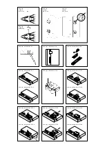
für alle gängigen nach innen öffnenden Türen (Abb. 2). Die Montage
kann auf den Werkstoffen Holz, Kunststoff oder Alu erfolgen.
Die Türen können nach rechts oder links öffnen (Abb. 2a).
Achtung: Die Tür darf nicht weiter als 90
°
geöffnet werden.
Der Drehpunkt der Tür muss mindestens 8 mm von der Falzkante
entfernt liegen.
TAS 112 wird grundsätzlich auf der Innenseite montiert,
das Führungsblech auf dem Türblatt und das Gelenkmodul auf
dem Rahmen. Zusätzlich sollen auf der Griffseite der Tür geeignete
Zusatzsicherungen montiert werden.
Achtung: Befestigungshinweis:
Zum Erreichen einer besonders hoch belastbaren Verankerung
an Holz und Kunststoffrahmen den mitgelieferten Poweranker
verwenden. Bei Metallzargen empfiehlt sich die Verwendung von
ABUS Befestigungsanker BA oder das ABUS Befestigungsset IM 100.
Zu IM 100 wird ein geeigneter Verbundmörtel z. B. der Marke
Fischer FIS VS 150C, Hilti HFX oder ein ähnliches Produkt benötigt.
ABUS BA und ABUS IM 100 sowie Verbundmörtel sind im Handel
erhältlich.
Die in Abb. 2b zusätzlich gezeigten ABUS-Produkte sind ebenfalls
im Handel erhältlich.
(NL):
Bei Kunststoffrahmen sollte eine Metalleinlage von min.
1,5 mm vorhanden sein. Falls nicht, ist der Einbau von 2 Stück BA
für dieses Produkt gemäß SKG-Anforderung in den Niederlanden
vorgeschrieben. ABUS BA und ABUS IM 100, sowie Verbundmörtel
sind ebenfalls im Handel erhältlich.
III. Packungsinhalt
(Abb. 3)
1. 1 Gelenkmodul – Achtung: Gelenkmodul zusammenhalten
1
(mit Gummiring geliefert)
2. 1 Führungsblech
3. 1 Abdeckhaube für Führungsblech
4. 2 Poweranker
5. 2 Rahmendübel mit Schrauben 8 x 120 mm
6. 1 Rahmenabdeckung
7. 1 Unterlage (auch Bohrschablone)
8. Schrauben:
2 Stück M6 x 22 mm
2 Stück 4,8 x 15 mm
2 Stück M6 x 27 mm
4 Stück 4,8 x 32 mm
2 Stück M6 x 30 mm
2 Stück 4,8 x 50 mm
2 Stück M6 x 32 mm
4 Stück 5,5 x 50 mm
IV. Montagewerkzeug
Kreuzschlitzschraubendreher
Bohrmaschine
Feile, Säge zum Kürzen der Schrauben, ggf. Schraubstock
Steinbohrer 8 mm Ø (für 120 mm Tiefe)
Forstnerbohrer 20 mm Ø (für Poweranker)
V. Montageanleitung:
Wichtige Hinweise:
•
Vor der Montage prüfen Sie bitte die Einstellung der Tür.
Stellen Sie sicher, dass sich die Tür die einwandfrei öffnen
und schließen lässt.
•
Die Bohrlochtiefen bzw. die Schraubenlängen müssen auf die
örtlichen Gegebenheiten abgestimmt werden.
•
Austreten des Bohrers bzw. der Schrauben auf der Rückseiten
vermeiden! Ggf. mit Bohranschlag arbeiten oder die vorhan-
denen Schrauben kürzen.
•
Beim Bohren keine beweglichen Teile, Dichtungen oder Glas-
scheiben beschädigen.
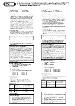
for
screws
Ø
in wood or
synthetic materials
without
metal liner
drill bit Ø
in aluminium and
synthetic materials
with
metal liner
drill bit Ø
3.5 mm
4.0 mm
4.0 mm
4.5 mm
4.8 mm
5.5 mm
Drilling Table
G
This instruction is divided into the following sections:
I.
General Information
IV. Tools
II. Application Options
V. Installation Instruction
III. Package Contents
VI. Operation
I.
General Information
The hinge-side safety device for doors and windows TAS 112 is
certified according to DIN 18 104-1 and VdS 2536. TAS 112 has
been certified as a “DIN tested BURGLAR RETARDANT” by DIN
Certco. TAS 112 offers additional protection against unauthorized
room access. According to DIN 18 104-1, the installation of
2 additional safety devices, one each on the left and the right side,
is recommended per meter door height (with at least one safety
device per door needing to be lockable). The police and insurance
companies also recommend these measures.
Optimal protection is only achievable if the procedures described
in this installation and operating instruction are followed.
To avoid overtightening, fastening screws should be screwed in
with a suitable tool and tightened by hand. Only use ABUS mounting
materials.
The manufacturer does not assume any liability for any damages
and/or injuries sustained during installation and/or through
inappropriate handling.
The possibility to open one entrance of the overall object from the
outside with a key must exist.
II. Application Options
TAS 112 is installed at the door’s hinge side and is suitable for
all common doors opening towards the room interior (fig. 2).
Installation can be carried out on wood, synthetic materials or alu-
minium. The doors may open towards the left or the right (fig. 2a).
Please note: The door may not open any further than 90
°
.
The distance between the door’s pivot point and the rebate
edge needs to be at least 8 mm.
TAS 112 is principally mounted on the inside, the guidance plate
is mounted on the door leaf and the joint module on the frame.
Suitable supplementary safety devices should additionally be
installed on the door’s handle side.
Please note: Installation advice:
Please use the power anchor included to achieve a particularly
tough and load-resistant fastening on wood or synthetic frames.
For metal frames, using the ABUS fastening anchor BA or the
ABUS fastening set IM 100 is recommended. With IM 100,
a suitable composite mortar such as Fischer FIS VS 150C, Hilti HFX
or a similar product is required.
ABUS BA and ABUS IM 100 as well as the mortar are commercially
available.
The additional ABUS products shown in fig. 2b are also
commercially available.
(NL):
A metal lining of at least 1.5 mm should be provided with
synthetic frames. If it is not already provided, the installation of
2 pieces BA is required for this product according to SKG specifi-
cations in the Netherlands. ABUS BA and ABUS IM 100 as well as
the composite mortar are also commercially available here.
III. Package Contents
(fig. 3)
1. 1 Joint module – Note: hold joint module together
1
(with included rubber ring)
2. 1 Guidance plate
3. 1 Guidance plate cover
4. 2 Power anchors
5. 2 Frame plugs with screws 8 x 120 mm
6. 1 Frame cover
7. 1 Underlay (also drilling template)
8. Screws:
2 pieces M6 x 22 mm
2 pieces 4.8 x 15 mm
2 pieces M6 x 27 mm
4 pieces 4.8 x 32 mm
2 pieces M6 x 30 mm
2 pieces 4.8 x 50 mm
2 pieces M6 x 32 mm
4 pieces 5.5 x 50 mm
IV. Installation Tools
Crosshead screwdriver
Power drill
File and/or saw for shortening the screws, a vice, if required
Stone drill Ø 8 mm (for 120 mm depth)
Forstner bit Ø 20 mm (for power anchor)
V. Installation Instructions
Important advice:
•
Please review the door adjustment before installation.
Ensure that the door can be opened and closed perfectly.
•
Drill hole depths or screw lengths, respectively,
need to be adjusted to local conditions.
•
Please avoid the drill or screws, respectively,
emerging at the back.
If required, work with a drill stop or shorten the screws used.
•
Take care not to damage any movable parts,
seals or glass panes with the drill.
D
Montage- und Bedienungsanleitung für ABUS Fenster-Scharnierseiten-Sicherung TAS 112
G
Installation and Operating Instructions for ABUS hinge-side window safety device TAS 112


