19
English
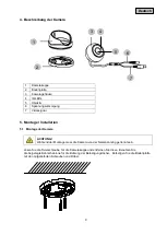
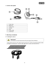
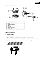
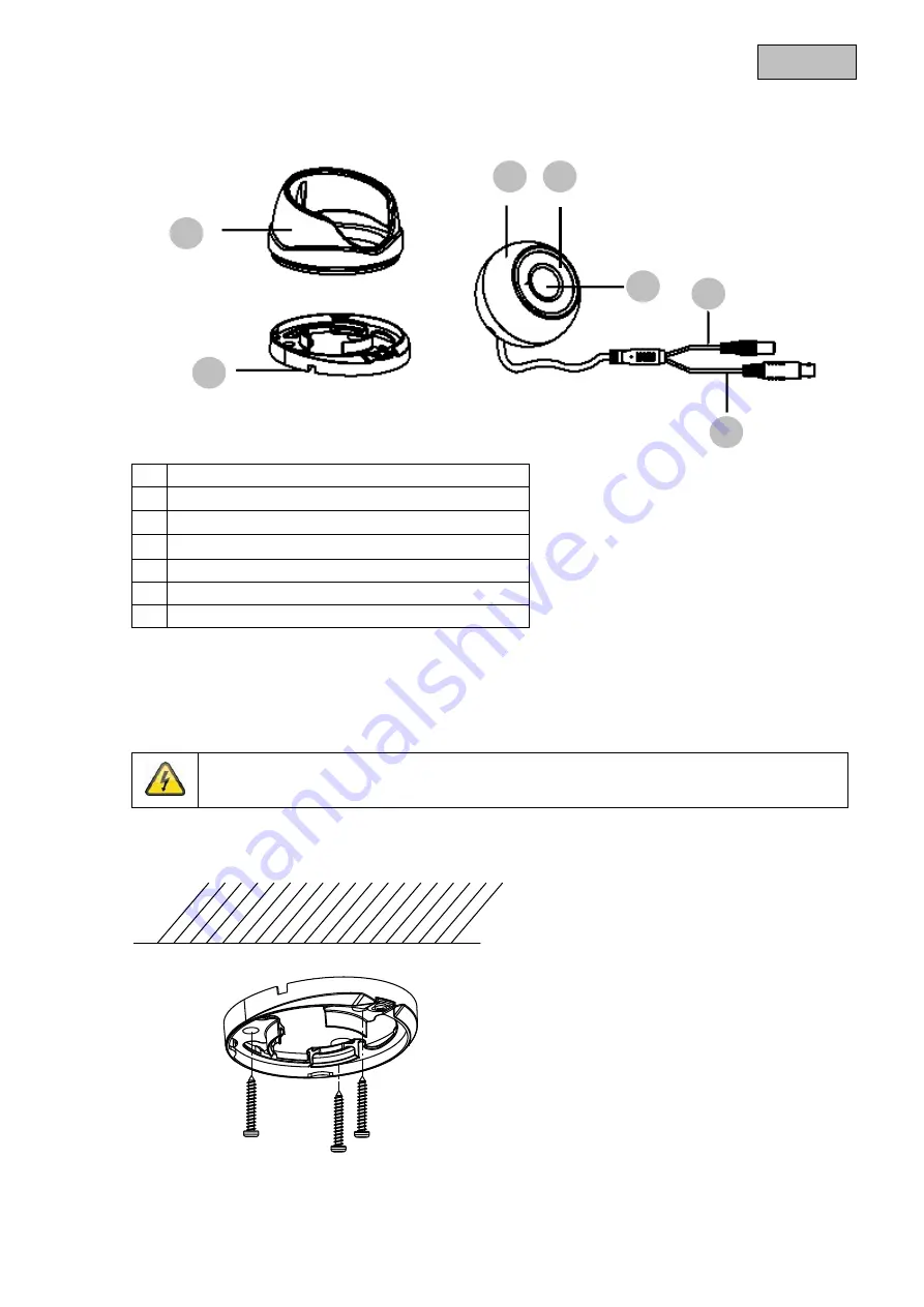
4. Camera description
1
Camera cap
2
Base plate
3
Camera body
4
IR LEDs
5
Lens
6
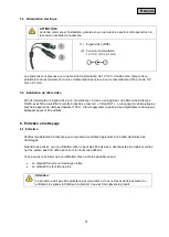
Power supply
7
Video signal
5. Mounting / installation
5.1 Mounting the camera
IMPORTANT!
The camera must be disconnected from the power supply during installation.
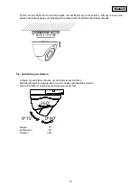
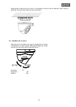
Loosen the fixing screws for the camera cap and remove them. Use the accompanying drilling template
for drilling the mounting holes. Secure the base plate with the screws and dowels provided.
1
2
3
4
5
6
7
Summary of Contents for TVCC34020
Page 93: ...TVCC34020 02 2014...
Page 95: ...95 CE...
Page 96: ...96 1 100 240 V AC 50 60 12 V DC 1 5 A 2 3 1 2 3...
Page 97: ...97 1 98 2 98 3 98 4 99 5 99 5 1 99 5 2 100 5 3 101 5 4 101 6 101 6 1 101 6 2 102 7 102 8 102...
Page 98: ...98 1 IP66 3 2 12 V DC 1 5 A 20 3 IP66 600 TVL TVVR30004 TVVR30104...
Page 99: ...99 4 1 2 3 4 5 6 7 5 5 1 1 2 3 4 5 6 7...
Page 100: ...100 5 2 360 0 90 0 75 75 90 360...
Page 101: ...101 5 3 1 BNC 2 12 V DC 5 5 x 2 1 12 V DC 5 5 x 2 1 5 4 RG59 BNC Video OUT 150 6 6 1 1 2...

