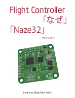
Mini FunFly Flight Controller “Naze32” (
なぜ)
Motor Mixer Settings
1
2
3
4
1
2
3
4
4
5
6
3
1
2
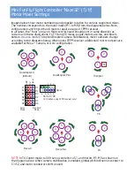
Images below show motor numbering and propeller rotation for various supported mixes.
The number corresponds to the motor index (M1 to M8) from the diagrams below. Note,
configurations with more than 6 motors require usage of CPPM receiver.
In all cases, the “front” arrow on flight control board should point in same direction as
red arrow in these illustrations. For Y4 and Y6 mixes, purple motors are top, and blue is
bottom. In
servo mode
(Tricopter/Bicopter/Camera Stabilization), motor numbers change
according to the diagrams below. When using CPPM receiver additional 4 motor outputs are
available for Hexa + Camera, or Octo configuration.
QuadCopter-X
(default)
QuadCopter-Plus
1
4
2
3
Y4
4
3
1
5
6
2
Hexa-Plus
4
6
1
2
3
5
Hexa-X
Y6
3
1
2
S1
TriCopter
M1
M2
M3
M4
M5
M6
GND
5V
Signal
S1
S2
M1
M2
M3
M4
NOTE
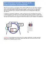
In Tri-Copter mode, tail tilt servo connects to S1, and motors M1..M3 as shown on
the diagram above. When camera stabilization is enabled, gimbal pitch/roll servos connect to
S1/S2, and motor connectors shift as well.
1 2 3
4 5 6 7 8
M5 M6 M7 M8
NOTE
: When using CPPM receiver only!
Signal
Servo
Mode
Standard
Mode

