15
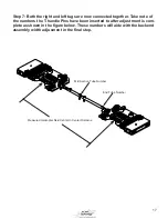
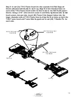
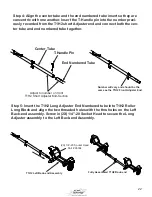
Step 4: Align the center numbered #1 thru hole and one end of the center
tube shown and insert the T-handle pin (Part #95545) far enough until the
handle cannot slide out freely. Remove the T-Handle Pin on the side with
the adjustment handle and leave out until the tug’s width has been adjusted
to the previously measured width. This connection does not adjust and will
remain intact when adjusting the width of the T1H2 tug. Facing down on the
adjusment handle turn it counter-clockwise until it can no longer turn.
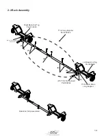
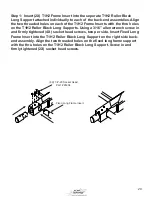
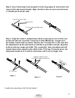
Step 3: Align the thru holes on both the center numbered tube and end of
the tube shown and insert T-handle pin (Part #95545) far enought until the
handle cannot slide out freely. Take note this pin will be removed and ad-
justed in step 6 of this process when connecting both the right and left tugs.
#1 Thru Hole
Figure 1
Figure 2
Figure 3
Center Tube


